1. Introduction
This manual provides detailed instructions for the installation, operation, and maintenance of the HiLetgo MTS102 SPDT (Single Pole Double Throw) 2-position toggle switch. Designed for various electronic applications, this non-momentary switch offers reliable ON/ON functionality for both low and high voltage circuits.
2. Product Overview and Features
The HiLetgo MTS102 is a compact and versatile toggle switch suitable for a wide range of applications, including automotive electronics, communication equipment, testing instruments, and various household appliances. Each package contains 10 units of the MTS102 switch.

Figure 2.1: Ten HiLetgo MTS102 toggle switches.
Key Features:
- Switch Type: SPDT (Single Pole Double Throw) Latching
- Positions: 2 (ON/ON)
- Terminals: 3
- Voltage & Current Rating: AC 125V, 6A
- Thread Diameter: 6mm / 0.24 inches
- Main Body Size: 13 x 10mm / 0.5 x 0.4 inches (Length x Width)
- Overall Height: 33mm / 1.3 inches
- Non-Momentary Operation: The switch maintains its position until manually changed.
3. Specifications
| Attribute | Value |
|---|---|
| Brand | HiLetgo |
| Model Number | 3-02-0667-10pcs |
| Switch Type | SPDT (Single Pole Double Throw) |
| Positions | 2 (ON/ON) |
| Terminals | 3 |
| Voltage Rating | AC 125V |
| Current Rating | 6A |
| Mounting Type | Surface Mount (Threaded Bushing) |
| Material | Metal (Lever), Plastic (Body) |
| Package Dimensions | 2.52 x 1.85 x 0.75 inches |
| Item Weight | 1.59 ounces (for 10pcs) |
4. Setup and Installation
The MTS102 toggle switch is designed for easy installation into panels or enclosures. Proper wiring and soldering techniques are crucial for reliable operation and to prevent damage to the switch.
4.1 Mounting the Switch
- Prepare Panel Hole: Drill a 6mm (0.24 inch) diameter hole in your panel or enclosure where the switch is to be mounted.
- Insert Switch: Insert the threaded bushing of the switch through the prepared hole.
- Secure with Nut: Place the washer and then thread the retaining nut onto the bushing from the front of the panel. Tighten the nut securely to hold the switch in place. Do not overtighten.

Figure 4.1: Close-up view of a single MTS102 toggle switch.
4.2 Wiring and Soldering
The MTS102 is a SPDT switch with three terminals. Understanding the terminal configuration is essential for correct wiring:
- Common Terminal: This is typically the center terminal.
- Normally Open (NO) Terminal: Connected to the common terminal when the switch is in one ON position.
- Normally Closed (NC) Terminal: Connected to the common terminal when the switch is in the other ON position.
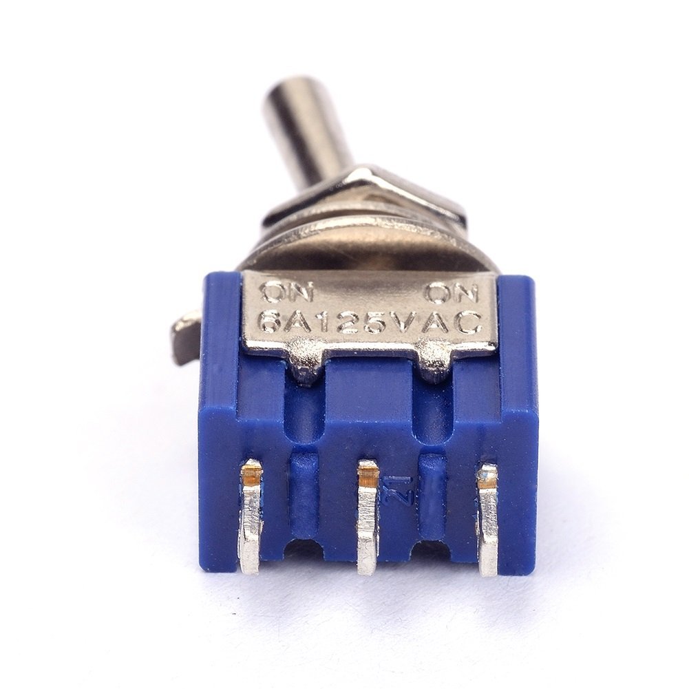
Figure 4.2: Terminals of the MTS102 switch.
Important Soldering Precautions:
- Use Appropriate Temperature: The plastic body of the switch has a relatively low melting point. Use a soldering iron with a controlled temperature, ideally around 370-380°C (698-716°F).
- Minimize Heat Exposure: Apply heat to the terminals for the shortest possible duration. Rapid soldering is recommended.
- Tin Leads and Wires: Pre-tinning both the switch terminals and the wires before making the connection will facilitate quicker and more efficient soldering, reducing heat exposure.
- Lever Position: When soldering, it is advisable to switch the lever to a position where the terminal you are soldering to is not actively engaged, reducing internal spring pressure on that terminal.
- Avoid Excessive Force: Do not apply excessive mechanical force to the terminals during or after soldering, as this can dislodge them from the plastic housing.
5. Operating Instructions
The HiLetgo MTS102 is a 2-position (ON/ON) latching toggle switch. This means it has two stable states, and it will remain in the position it is set to until manually moved to the other position.
- Position 1 (ON): Push the toggle lever to one side. In this position, the common terminal will be connected to one of the outer terminals (e.g., the Normally Open terminal).
- Position 2 (ON): Push the toggle lever to the opposite side. In this position, the common terminal will be connected to the other outer terminal (e.g., the Normally Closed terminal).
This switch is ideal for applications where you need to switch between two different circuits or states, such as selecting between two power sources, controlling two different functions, or reversing polarity in certain low-current applications.
6. Maintenance
The HiLetgo MTS102 toggle switches are designed for durability and generally require minimal maintenance. However, following these guidelines can help ensure their longevity:
- Keep Clean: Ensure the switch and its surrounding area are free from dust, dirt, and debris, which can interfere with mechanical operation.
- Avoid Moisture: Protect the switches from excessive moisture or corrosive environments, as this can lead to corrosion of contacts and terminals.
- Inspect Connections: Periodically check soldered connections for any signs of loosening or corrosion, especially in applications subject to vibration.
- Do Not Overload: Ensure the current and voltage ratings of the switch (AC 125V, 6A) are not exceeded in your application to prevent premature failure.
7. Troubleshooting
If you encounter issues with your HiLetgo MTS102 toggle switch, consider the following common problems and solutions:
| Problem | Possible Cause | Solution |
|---|---|---|
| Switch not functioning (no continuity) | Poor solder joint; dislodged terminal; internal damage from overheating during soldering; incorrect wiring. | Inspect solder joints and re-solder if necessary, ensuring minimal heat exposure. Verify wiring against circuit diagram. If terminal is dislodged or switch is internally damaged, replace the switch. |
| Switch feels loose or wobbly after installation | Mounting nut not tightened sufficiently; plastic housing deformed. | Ensure the retaining nut is securely tightened. If the plastic housing is deformed from overtightening or heat, the switch may need replacement. |
| Switch lever is stiff or difficult to move | Debris inside mechanism; physical damage. | Ensure no foreign objects are obstructing the lever. If the issue persists, the switch may be damaged and require replacement. |
| Switch melts or deforms during soldering | Soldering iron temperature too high; excessive heat application time. | Use a temperature-controlled soldering iron (approx. 370-380°C). Apply heat quickly and efficiently. Pre-tin wires and terminals. Replace the damaged switch. |
8. Warranty and Support
HiLetgo products are manufactured to high quality standards. For specific warranty information or technical support, please refer to the official HiLetgo website or contact their customer service directly. Keep your purchase receipt for any warranty claims.
HiLetgo Official Website: www.hiletgo.com
Customer Support Email: support@hiletgo.com

Figure 8.1: HiLetgo product packaging.


