Logilink PDU8P01
Logilink PDU8P01 8-Port IP Power Distribution Unit User Manual
Model: PDU8P01
1. Introduction
The Logilink PDU8P01 is an advanced 8-port IP Power Distribution Unit designed for efficient power management in server racks and data centers. This device allows for remote control of individual power outlets, comprehensive power monitoring, and environmental sensing (temperature and humidity). This manual provides essential information for the safe and effective installation, configuration, and operation of your PDU8P01.
2. Safety Information
Please read and understand all safety instructions before installing or operating the PDU8P01. Failure to follow these instructions may result in electric shock, fire, or damage to the equipment.
- Ensure the PDU is connected to a properly grounded power source.
- Do not open the PDU casing. There are no user-serviceable parts inside.
- Avoid operating the PDU in excessively humid or hot environments.
- Do not overload the PDU. Refer to the specifications for maximum load capacity.
- Disconnect power before performing any maintenance or installation procedures.
- Use only the provided or recommended power cables.
3. Package Contents
Verify that all items are present and in good condition upon unpacking.
- Logilink PDU8P01 8-Port IP Power Distribution Unit
- C19 to C20 Power Cable
- User Manual (this document)
- Mounting hardware for 19-inch rack installation (may vary by region/package)

Image 1: Front view of the Logilink PDU8P01, showing the C19 input and eight C13 outlets, along with the display and network port.
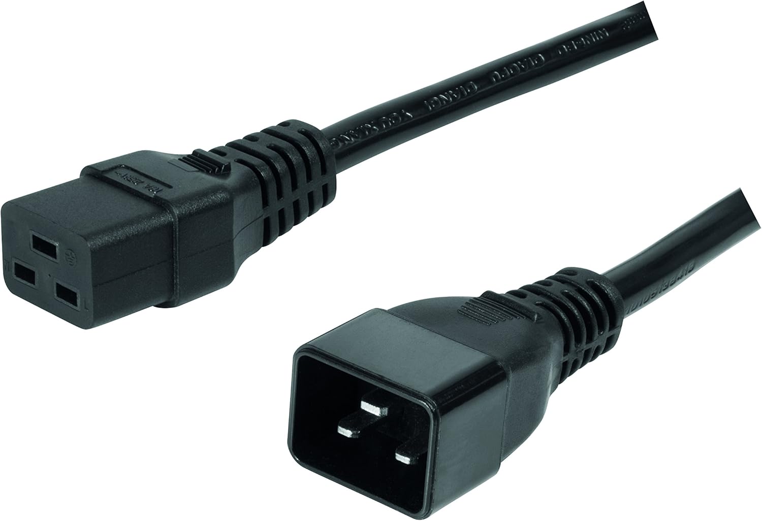
Image 2: Included C19 to C20 power cable for connecting the PDU to a power source.
4. Product Overview
4.1 Front Panel
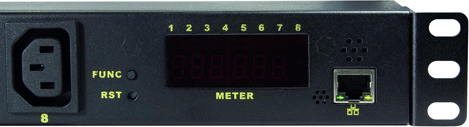
Image 3: Close-up of the PDU's front panel, highlighting the display, function buttons, and network port.
- C19 Input (INPUT 1): Main power input connector.
- C13 Outlets (1-8): Eight individually controllable power outlets.
- FUNC Button: Used to cycle through display information (e.g., IP address, voltage, current, temperature, humidity).
- RST Button: Reset button for the PDU.
- LED Display (METER): Shows various operational parameters and network information.
- RJ45 Ethernet Port: For network connection and IP management.
- Outlet Status LEDs (1-8): Indicate the on/off status of each C13 outlet.
5. Setup
5.1 Physical Installation
- Mount the PDU into a standard 19-inch server rack using the provided mounting hardware. Ensure it is securely fastened.
- Connect the C19 end of the included power cable to the PDU's C19 input port.
- Connect the C20 end of the power cable to a suitable power source (e.g., UPS, wall outlet with C20 receptacle).
- Connect an Ethernet cable from the PDU's RJ45 port to your network switch or router.
- Plug your devices into the C13 outlets (1-8) on the PDU.
5.2 Initial Network Configuration
- Power on the PDU. The LED display will illuminate.
- Press the FUNC button repeatedly until the IP address is displayed on the meter. The default IP address is typically 192.168.0.100.
- Open a web browser on a computer connected to the same network segment as the PDU.
- Enter the PDU's IP address (e.g., http://192.168.0.100) into the browser's address bar and press Enter.
- You will be prompted for a username and password. The default credentials are often:
- Username: admin
- Password: admin or password
- Once logged in, you can configure network settings (e.g., static IP, DHCP), change user credentials, and manage other PDU settings.
6. Operating Instructions
6.1 Web Interface Overview
The web interface provides comprehensive control and monitoring capabilities. Navigate through the menus to access different functions.
6.2 Outlet Control
- Switching Outlets: From the web interface, you can individually turn each of the 8 C13 outlets ON or OFF.
- Power-On Sequencing: Configure delays for outlets to power on sequentially. This prevents inrush current overloads when multiple devices start simultaneously.
- Scheduled Operations: Set schedules for outlets to turn on or off at specific times.
6.3 Monitoring
The PDU allows real-time monitoring of various parameters:
- Voltage (V): Input voltage.
- Current (A): Total current draw.
- Power (W): Total power consumption.
- Temperature (°C/°F): Ambient temperature via integrated sensor.
- Humidity (%): Ambient humidity via integrated sensor.
These values can be viewed on the PDU's LED display by pressing the FUNC button, or more comprehensively through the web interface.
6.4 Alert and Warning Functions
Configure thresholds for voltage, current, power, temperature, and humidity. If these thresholds are exceeded, the PDU can trigger alerts (e.g., email notifications) to inform administrators of potential issues.
7. Maintenance
- Cleaning: Periodically clean the exterior of the PDU with a soft, dry cloth. Do not use liquid cleaners or solvents. Ensure the PDU is powered off and disconnected before cleaning.
- Firmware Updates: Check the Logilink support website for any available firmware updates. Follow the instructions provided with the firmware update package carefully.
- Cable Management: Ensure all power and network cables are neatly organized and not obstructing airflow.
8. Troubleshooting
| Problem | Possible Cause | Solution |
|---|---|---|
| PDU does not power on. | No power to the C19 input. | Check the power cable connection and the power source. Ensure the C20 receptacle is live. |
| Cannot access web interface. | Incorrect IP address, network connectivity issue, or incorrect credentials. |
|
| Outlets not switching. | Software issue, PDU overload, or internal fault. |
|
| Inaccurate sensor readings. | Environmental interference or sensor malfunction. | Ensure the PDU is not in direct sunlight or near heat sources. If issues persist, contact support. |
9. Specifications
| Feature | Detail |
|---|---|
| Model | PDU8P01 |
| Brand | Logilink |
| Input Connector | 1 x C19 |
| Output Connectors | 8 x C13 |
| Form Factor | 1U Rackmount |
| Network Interface | RJ45 Ethernet (10Mbit) |
| Monitoring | Voltage, Current, Power, Temperature, Humidity |
| Special Features | Surge Protection, Remote Outlet Control, Power-On Sequencing, Alert Functions |
| Product Dimensions | 18.96 x 1.77 x 1.77 inches (48.16 x 4.5 x 4.5 cm) |
| Item Weight | 5.21 pounds (2.36 kg) |
10. Warranty and Support
For warranty information and technical support, please refer to the official Logilink website or contact your local distributor. Keep your purchase receipt as proof of purchase.
Logilink Website: www.logilink.com (This is a placeholder, actual link may vary)
Ask a question about this manual
Ask about setup, troubleshooting, compatibility, parts, safety, or missing instructions. Manuals+ will review the question and use this page’s manual context to help answer it.