1. Product Overview
The NOYITO Digital Temperature Controller Module is a high-precision device designed for various temperature control systems. It features a green LED display for clear temperature readings and comes with a 1-meter NTC waterproof metal sensor probe. This module supports both heating and cooling control modes and offers adjustable parameters for precise temperature management.
- Display: Green LED
- Temperature Range: -58℉ to +257℉
- Resolution: 0.1℉ for -3.9℉ to 99.9℉, 1℉ for other ranges
- Measurement Accuracy: ±1℉
- Backlash Accuracy: 0.1℉
- Refresh Rate: Approximately 0.5 seconds
- Relay Load: DC 14V 20A / AC 125V 20A
- Working Voltage: DC 24V
- Sensor: 1 meter NTC (10K 0.5%) waterproof metal sensor
2. Setup and Wiring
Proper wiring is crucial for the safe and correct operation of the temperature controller. Ensure all connections are secure and match the diagrams provided. The module requires a DC 24V power supply.
2.1 Circuit Connection
Connect the power supply and the load according to the circuit diagrams. The digital display will show the actual measured temperature once powered. If the display shows "---", check if the temperature sensor is properly installed or if it is damaged.

Figure 2.1: Wiring diagrams for controlling AC and DC heating/cooling devices, and powering the module and device simultaneously.
- Power Supply (VCC, GND): Connect your DC 24V power source to the VCC (positive) and GND (negative) terminals on the module.
- Load Connection (K0, K1): The relay contacts K0 and K1 are used to control your heating or cooling device. These contacts act as a switch. Connect your load (e.g., heater, fan) through these terminals. The maximum load capacity is DC 14V 20A or AC 125V 20A.
- Sensor Connection: The NTC waterproof sensor probe connects to the dedicated two-pin connector on the module. Ensure it is firmly seated.
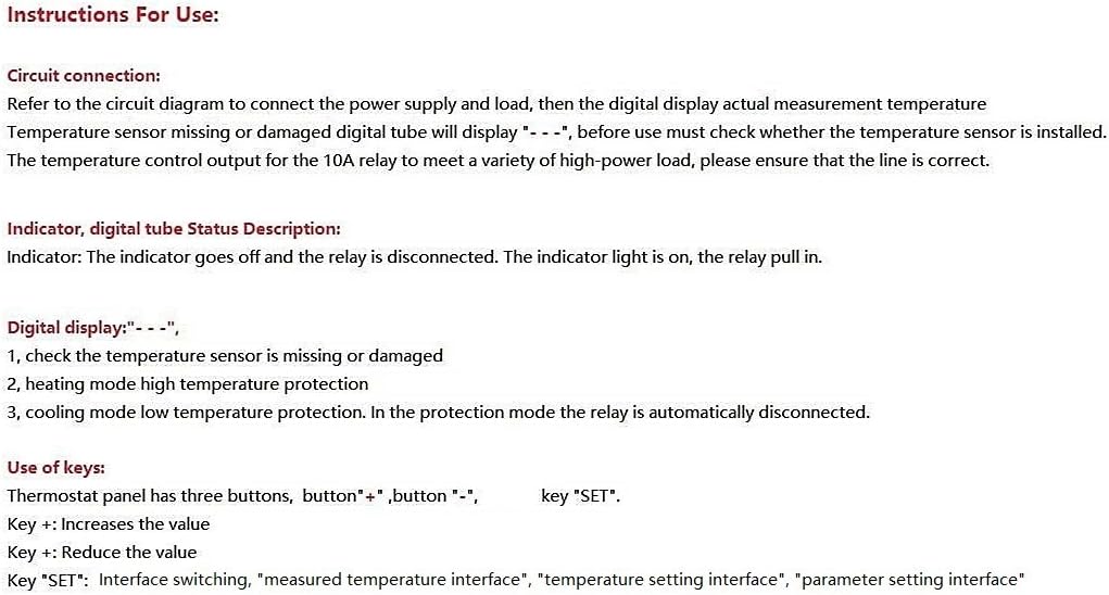
Figure 2.2: The NOYITO Digital Temperature Controller Module with the NTC sensor connected.
3. Operating Instructions
The thermostat panel has three buttons: "+", "-", and "SET".
3.1 Key Functions
- Key "+": Increases the value.
- Key "-": Reduces the value.
- Key "SET": Used for interface switching (measured temperature, temperature setting, parameter setting).
3.2 Setting the Target Temperature
In the normal temperature display mode:
- Short Press "SET": The digital display will start flashing, indicating you are in the temperature setting interface.
- Adjust Temperature: Use the "+" or "-" buttons to set your desired target temperature.
- Save Settings: After setting, either short press "SET" again to save the data, or wait 5 seconds for the data to be saved automatically.
3.3 Parameter Settings (P0-P4)
To access advanced parameters:
- Long Press "SET": Hold the "SET" button for several seconds to enter the parameter setting interface. The display will show P0.
- Navigate Parameters: Use the "+" or "-" buttons to switch between parameters P0 to P4.
- Edit Parameter: Once the desired parameter (e.g., P0) is displayed, short press "SET" to enter its setting mode. The value will flash.
- Adjust Value: Use the "+" or "-" buttons to change the parameter's value.
- Save Parameter: Long press "SET" to save the new value and exit the parameter setting mode, or wait 6 seconds for automatic saving.

Figure 3.1: Detailed instructions for use, including key functions and parameter settings.
| Parameter Setting | Function Description | Set Range | Factory Setting |
|---|---|---|---|
| P0 | Cooling / Heating Mode | C/H | C (Cooling) |
| P1 | Hysteresis Setting | 32℉ - 68℉ | 2 |
| P2 | Temperature Correction | 14℉ - 50℉ | 0 |
| P3 | Set Run Time | 0 - 240 Minutes | OFF |
| P4 | Set Stop Time | 0 - 240 Minutes | OFF |
Note on P3 and P4:
- P3 setting "1" means the thermostat will run for 1 minute, then stop. Long press SET to trigger it again.
- P4 setting "1" indicates that the thermostat starts working after 1 minute. The digital tube will not light up until 1 minute after the normal work. Press SET repeatedly to trigger again.
3.4 Indicator and Digital Display Status
- Indicator Light: The indicator light is ON when the relay is activated (pull-in). The indicator light is OFF when the relay is disconnected.
- Digital Display "---": This indicates a problem with the temperature sensor. Check if the sensor is missing or damaged. It can also indicate high temperature protection in heating mode or low temperature protection in cooling mode, in which case the relay is automatically disconnected.
4. Maintenance
To ensure the longevity and accurate performance of your NOYITO Digital Temperature Controller Module, follow these maintenance guidelines:
- Keep Clean: Regularly clean the module and sensor to prevent dust and debris buildup, which can affect performance. Use a soft, dry cloth.
- Avoid Moisture: Although the sensor is waterproof, the module itself is an unprotected circuit board. Keep the module in a dry environment and protect it from condensation.
- Check Connections: Periodically inspect all wiring connections for looseness or corrosion. Secure any loose connections.
- Environmental Conditions: Ensure the module operates within the specified environmental temperature (14℉ - 140℉) and humidity (20% to 75% RH).
5. Troubleshooting
This section addresses common issues you might encounter with the temperature controller module.
- Display shows "---": This indicates a problem with the temperature sensor. Check if the NTC sensor is properly connected to the module. Inspect the sensor cable for any damage. If the sensor is damaged, it may need replacement. This display can also indicate a protection mode (high temperature in heating, low temperature in cooling) where the relay is disengaged.
- Relay not activating/deactivating:
- Verify the power supply to the module is correct (DC 24V).
- Check the wiring to the load (K0, K1 terminals) for secure connections.
- Ensure the target temperature and hysteresis (P1) settings are appropriate for your application.
- Confirm the P0 parameter is set correctly for either cooling (C) or heating (H) mode.
- Check if P3 (Run Time) or P4 (Stop Time) parameters are enabled and affecting the relay operation.
- Inaccurate Temperature Readings:
- Ensure the sensor is correctly placed and making good contact with the area being measured.
- Use the P2 (Temperature Correction) parameter to calibrate the reading if a known accurate reference thermometer is available.
- Verify the sensor cable is not damaged or experiencing interference.
- Settings not saving after power off: The module is designed to retain settings after power loss. If settings are not retained, ensure the power supply is stable and the module is not experiencing intermittent power interruptions.
6. Specifications
| Feature | Specification |
|---|---|
| Product Name | High-precision Digital Temperature Control Module |
| Display Color | Green LED |
| Temperature Range | -58℉ to +257℉ |
| Resolution | 0.1℉ (-3.9℉ ~ 99.9℉), 1℉ (other ranges) |
| Temperature Measurement Accuracy | ±1℉ |
| Backlash Accuracy | 0.1℉ |
| Refresh Rate | Approx. 0.5 seconds |
| Relay Load | DC 14V 20A / AC 125V 20A |
| Thermostat Working Voltage | DC 24V |
| Measuring Input | 1 meter NTC (10K 0.5%) waterproof metal sensor |
| Module Working Environment Temperature | 14℉ - 140℉ |
| Module Working Environment Humidity | 20% to 75% RH |
| Dimensions (L*W*H) | 46 * 40 * 16mm (1.81 x 1.57 x 0.63 inches) |
| Weight | 30g (1.13 ounces) |
| Model Number | NODTC2458257 |
| UPC | 612957710590 |
7. Warranty and Support
7.1 Warranty Information
This NOYITO Digital Temperature Controller Module is covered by a Manufacturer's One-year After-sale Warranty. Please retain your proof of purchase for warranty claims.
7.2 Technical Support
For any technical assistance, questions, or issues not covered in this manual, please contact NOYITO customer support. Refer to the product packaging or the retailer's website for contact details.