
1. Product Overview
The RATTMMOTOR 80mm CNC Spindle Motor Clamp Mount Bracket is designed to securely hold 80mm diameter spindle motors, including 1.5KW and 2.2KW water-cooled and air-cooled models, for CNC router, engraver, and milling applications. Constructed from cast aluminum, this bracket offers high accuracy and durability compared to standard aluminum profile fixtures.
Key Features:
- Material: High-quality cast aluminum for enhanced strength and precision.
- Surface Treatment: Sandblasted finish for improved anti-oxidation properties and aesthetic appeal.
- Design: Features an anti-slip silk structure to prevent spindle motor slippage during operation.
- Compatibility: Specifically designed for Φ80mm diameter high-speed spindle motors.
- Durability: Offers a long service life with scientific casting, pressure resistance, noise reduction, and anti-static design.

Image 1.1: Overview of the CNC Spindle Motor Clamp Mount Bracket highlighting its robust construction and features.
2. Specifications
The following table details the physical specifications of the 80mm spindle motor clamp bracket.
| Specification | Value |
|---|---|
| Model Number | 80CP |
| Material | Cast Aluminum |
| Finish Type | Brushed, Sandblasted |
| Mounting Type | Wall Mount (typical for CNC gantry) |
| Product Dimensions (L x W x H) | 5.83 x 3.07 x 3.15 inches (148 x 78 x 80 mm) |
| Item Weight | 3.03 pounds (1.38 Kilograms) |
| Compatible Spindle Diameter | 80mm |
| Included Components | 1 Spindle Motor Clamp, 3 Screws |

Image 2.1: Dimensional drawing of the 80mm clamp, showing key measurements including 80mm inner diameter, 148mm length, and 78mm width.

Image 2.2: Comprehensive specification table for various clamp sizes, including the 80mm model's 'a', 'b', 'c', 'd', 'e', 'f', 'g' dimensions in millimeters.
3. Setup and Installation
Proper installation of the spindle motor clamp is crucial for stable and accurate CNC operation. Follow these steps for secure mounting.
3.1 Unpacking and Inspection
- Carefully remove the clamp and screws from the packaging.
- Inspect all components for any signs of damage during transit. Contact customer support if any damage is found.
- Verify that all included items (1 clamp, 3 screws) are present.
3.2 Mounting the Clamp to the CNC Machine
- Identify the desired mounting location on your CNC machine's gantry or Z-axis assembly. Ensure the surface is flat and robust enough to support the spindle motor and clamp.
- The clamp features a flat base for secure attachment. Mark the positions for mounting holes on your machine based on the clamp's base dimensions.
- Drill appropriate pilot holes and tap them if necessary, ensuring they align with the clamp's mounting points.
- Secure the clamp to the CNC machine using suitable bolts (not included) that pass through the clamp's base and into the prepared mounting holes. Tighten these bolts firmly to prevent any movement.
3.3 Installing the Spindle Motor
- Loosen the three hex screws located on the top of the clamp. This will allow the clamp to open slightly.
- Carefully insert your 80mm diameter spindle motor into the circular opening of the clamp. Ensure the spindle is seated correctly and aligned as desired.
- Gradually tighten the three hex screws. The screws serve two primary functions: two screws are used to fix the spindle motor securely, while the third screw is used for adjustment during installation to ensure a snug fit.
- Tighten the screws evenly and firmly to ensure the spindle motor is held without any play. Do not overtighten, as this could damage the spindle motor casing or the clamp.
- The anti-slip silk design within the clamp helps maintain a firm grip on the spindle, reducing the risk of slippage during high-speed operation.
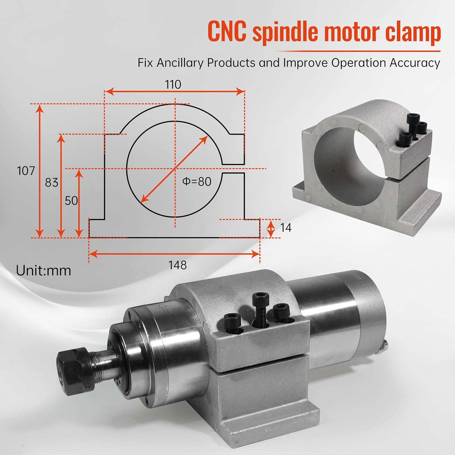
Image 3.1: The 80mm CNC spindle motor clamp shown with a spindle motor, illustrating how it fixes ancillary products and improves operation accuracy.

Image 3.2: Diagram explaining the function of the three screws: two for fixing the spindle motor and one for adjustment during installation.
4. Operation
Once the RATTMMOTOR 80mm Spindle Motor Clamp is securely installed and the spindle motor is mounted, its primary function is to provide rigid support during CNC operations.
- Ensure all mounting and clamping screws are tightened appropriately before initiating any machining tasks.
- Regularly check the tightness of the screws, especially after initial use and during prolonged operations, to maintain optimal stability.
- The robust cast aluminum construction and anti-slip design are intended to minimize vibration and deflection, contributing to higher machining accuracy.
5. Maintenance
To ensure the longevity and continued performance of your RATTMMOTOR spindle motor clamp, follow these simple maintenance guidelines:
- Cleaning: Periodically clean the clamp surface to remove dust, debris, and machining residue. Use a soft cloth; avoid abrasive cleaners that could damage the sandblasted finish.
- Screw Inspection: Inspect the hex screws for any signs of wear or damage. Replace any worn screws to ensure proper clamping force.
- Structural Integrity: Occasionally check the cast aluminum body for any cracks or deformities, especially if the machine has experienced impacts.
- Corrosion Prevention: The sandblasted surface treatment provides anti-oxidation properties. However, in humid environments, a light coating of rust preventative oil can be applied to the screws and exposed metal parts if needed.
6. Troubleshooting
This section addresses common issues that may arise during the use of the spindle motor clamp.
6.1 Spindle Motor Slippage
- Issue: The spindle motor rotates or shifts within the clamp during operation.
- Solution: Ensure all three hex screws on the clamp are tightened firmly and evenly. The anti-slip silk design should provide sufficient grip, but insufficient tightening is the most common cause of slippage. Verify that the spindle motor diameter is exactly 80mm.
6.2 Clamp Not Securing Spindle Properly
- Issue: The clamp does not hold the spindle motor tightly even after tightening the screws.
- Solution: Double-check that the spindle motor's outer diameter is precisely 80mm. If the spindle is undersized, the clamp may not be able to secure it adequately. Inspect the clamp's internal surface for any obstructions or damage that might prevent proper closure.
6.3 Mounting Instability
- Issue: The entire clamp assembly vibrates or moves on the CNC machine.
- Solution: Ensure the bolts securing the clamp to the CNC machine are fully tightened. Verify that the mounting surface on the CNC machine is flat and rigid. If necessary, consider adding a reinforcing plate between the clamp and the machine's gantry.
7. Warranty and Support
RATTMMOTOR products are manufactured to high standards. For any questions, technical assistance, or warranty claims, please refer to the official RATTMMOTOR store or contact their customer support directly.
Online Support: Visit the official RATTMMOTOR Store on Amazon for product information and support resources.