
1. Introduction
The Hongertem MF500 Analog Multimeter is a high-sensitivity, portable, rectifier-based instrument designed for measuring various electrical parameters. This device features twenty-four ranges, enabling precise measurements of AC and DC voltage, DC current, resistance, and audio levels. Its classic design, magnetic internal board head, bakelite shell, and overload protection ensure reliable and safe operation.
2. Safety Information
Always read and understand all safety instructions before operating the multimeter.
- Do not attempt to measure voltages or currents exceeding the specified maximum ratings of the device.
- Ensure the test leads are in good condition, free from cracks or damage, before each use.
- Never touch the metal tips of the test leads when connected to a circuit.
- Always disconnect power to the circuit before connecting or disconnecting test leads for resistance or current measurements.
- Use caution when working with high voltages. Always assume a circuit is live until proven otherwise.
- Replace batteries promptly when the low battery indicator appears to ensure accurate readings.
3. Product Overview
The MF500 Analog Multimeter features a clear analog display with a mirror feature scale for accurate readings, two rotary selector switches for function and range selection, and input jacks for test leads.

Figure 3.1: Front view of the MF500 Multimeter. Note the large analog display at the top, the two main rotary switches below it, and the input terminals at the bottom.

Figure 3.2: Detailed view of the control panel. The left knob selects voltage and resistance ranges, while the right knob selects current ranges and other functions.
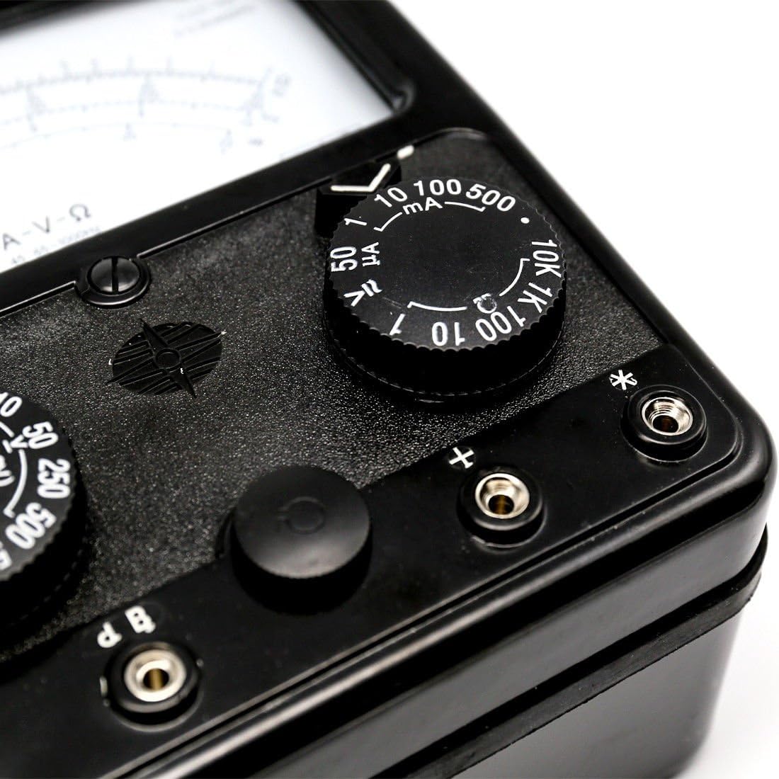
Figure 3.3: Close-up of the analog meter scale. The various arcs indicate different measurement types (A-V-Ω) and ranges, with a mirror strip for parallax error reduction.
4. Setup
4.1 Battery Installation
The MF500 Multimeter requires one 1.5V C battery and one 9V 6F22 battery for operation. These batteries are not included with the device.
- Locate the battery compartment cover on the back of the multimeter.
- Use a screwdriver to open the battery compartment.
- Insert the 1.5V C battery and the 9V 6F22 battery, ensuring correct polarity (+ and -).
- Replace the battery compartment cover and secure it.
4.2 Connecting Test Leads
The multimeter comes with a pair of test leads (red and black).
- Insert the black test lead into the common (COM) or negative (-) jack.
- Insert the red test lead into the positive (+) jack for most voltage, resistance, and low current measurements.
- For high current measurements (e.g., 500mA), refer to the specific jack labeled for higher current if available, or consult the markings on the device.
5. Operating Instructions
Before taking any measurement, ensure the multimeter is set to the correct function and range. Always start with a higher range and decrease it if necessary for more precise readings.
5.1 Measuring DC Voltage (DCV)
- Set the function switch to the DCV position.
- Select the appropriate range (e.g., 2.5V, 10V, 50V, 250V, 500V, 2500V). Choose a range higher than the expected voltage.
- Connect the red test lead to the positive (+) side of the circuit and the black test lead to the negative (-) side.
- Read the voltage value from the DCV scale on the analog display.
5.2 Measuring AC Voltage (ACV)
- Set the function switch to the ACV position.
- Select the appropriate range (e.g., 10V, 50V, 250V, 2500V). Choose a range higher than the expected voltage.
- Connect the test leads across the AC voltage source. Polarity is not critical for AC measurements.
- Read the voltage value from the ACV scale on the analog display.
5.3 Measuring DC Current (DCA)
Caution: Always connect the multimeter in series with the circuit for current measurements. Never connect it in parallel across a voltage source, as this can damage the meter.
- Turn off power to the circuit.
- Set the function switch to the DCA position.
- Select the appropriate range (e.g., 0.5mA, 1mA, 10mA, 100mA, 500mA). Start with the highest range if unsure.
- Break the circuit at the point where you want to measure current.
- Connect the red test lead to the higher potential side of the break and the black test lead to the lower potential side, completing the circuit through the multimeter.
- Restore power to the circuit.
- Read the current value from the DCA scale on the analog display.
- Turn off power and disconnect the multimeter before restoring the circuit.
5.4 Measuring Resistance (Ω)
Caution: Ensure the circuit is completely de-energized before measuring resistance. Measuring resistance on a live circuit can damage the multimeter.
- Turn off power to the circuit and discharge any capacitors.
- Set the function switch to the Ω (Ohms) position.
- Select the appropriate range (e.g., R2K, R20K, R200K, 2MΩ, 20MΩ).
- Touch the tips of the red and black test leads together to zero the meter. Adjust the 'Ω ADJ' knob if available, until the needle reads zero.
- Connect the test leads across the component or circuit section whose resistance you want to measure.
- Read the resistance value from the Ω scale on the analog display.
5.5 Measuring Audio Level (dB)
The MF500 Multimeter can measure audio levels, typically in decibels (dB), often integrated with AC voltage ranges. Refer to the specific markings on the dial for dB scales.
- Set the function switch to an appropriate ACV range that also indicates a dB scale.
- Connect the test leads across the audio signal source.
- Read the audio level from the dB scale on the analog display. Note that 0dB is typically referenced to 1mW into 600Ω.
6. Maintenance
- Cleaning: Wipe the multimeter with a dry, soft cloth. Do not use abrasive cleaners or solvents.
- Storage: Store the multimeter in a cool, dry place away from direct sunlight and extreme temperatures. Remove batteries if the device will not be used for an extended period.
- Battery Replacement: Replace batteries as described in the Setup section when readings become erratic or the meter does not power on.
- Test Leads: Inspect test leads regularly for any signs of damage, such as cracked insulation or exposed wires. Replace damaged leads immediately.
7. Troubleshooting
- No Display/Power: Check battery installation and ensure batteries are fresh.
- Inaccurate Readings: Ensure the correct function and range are selected. Check battery voltage. For resistance, ensure the meter is zeroed.
- Meter Not Responding: Verify test leads are properly connected and not damaged. Ensure the circuit is live for voltage/current measurements or de-energized for resistance.
- Overload Protection Activated: If the meter stops responding after an overload, disconnect it from the circuit and allow it to reset. Always use appropriate ranges to prevent overload.
8. Specifications
| Parameter | Specification |
|---|---|
| DC Voltage Ranges | 2.5V, 10V, 50V, 250V, 500V, 2500V |
| AC Voltage Ranges | 10V, 50V, 250V, 2500V |
| DC Current Ranges | 0.5mA, 1mA, 10mA, 100mA, 500mA |
| Resistance Ranges | R2K, R20K, R200K, 2MΩ, 20MΩ |
| Dimensions | 178 x 138 x 84 mm |
| Weight | Approximately 1450g |
| Power Supply | 1 x 1.5V C battery, 1 x 9V 6F22 battery (not included) |
| Features | High sensitivity, portable, rectifier-based, 24 ranges, mirror feature scale, classic design, magnetic internal board head, bakelite shell, overload protection. |
9. Warranty and Support
For warranty information and technical support, please refer to the documentation provided at the point of purchase or contact your retailer. Keep your purchase receipt as proof of purchase.