GODOX QS400II
Godox QS400II Studio Strobe Flash Light User Manual
Model: QS400II | Brand: GODOX
1. Introduction
The Godox QS400II Studio Strobe Flash Light is a professional-grade monolight designed for studio photography, offering 400Ws of power and a built-in 2.4G Wireless X System. This manual provides detailed instructions for the safe and effective use of your QS400II flash unit, ensuring optimal performance for various photographic applications including portrait, fashion, and product photography.

Figure 1.1: Godox QS400II Studio Strobe Flash Light and its components.
2. Safety Information
Please read and understand all safety precautions before using this product. Improper use can lead to electric shock, fire, or serious injury.
- Do not disassemble or modify the flash unit.
- Keep the unit dry. Do not expose to rain or moisture.
- Avoid direct eye exposure to the flash.
- Ensure the power supply matches the unit's requirements.
- Unplug the unit from the power outlet before cleaning or maintenance.
- Do not operate the unit near flammable gases or liquids.
3. Package Contents
Verify that all items listed below are included in your package:
- QS400II Flash Head x1
- Standard Reflector x1
- Glass Protective Cover x1
- Protection Case x1
- 150W Modeling Bulb x1
- Charger (Power Cable) x1
- Instruction Manual x1

Figure 3.1: Contents of the Godox QS400II package.
4. Product Overview
The QS400II features a robust design with intuitive controls for efficient operation.
4.1 Main Components
- Flash Tube: Provides the main light output.
- Modeling Bulb: A continuous light source for previewing lighting effects.
- Bowens Mount: Standard mount for attaching various light modifiers like reflectors, softboxes, and snoots.
- Control Panel: Features an LED display and buttons for adjusting settings.
- Mounting Bracket: For attaching the flash to a light stand.
- Direction Adjusting Handle: Allows for precise angle adjustments of the flash head.
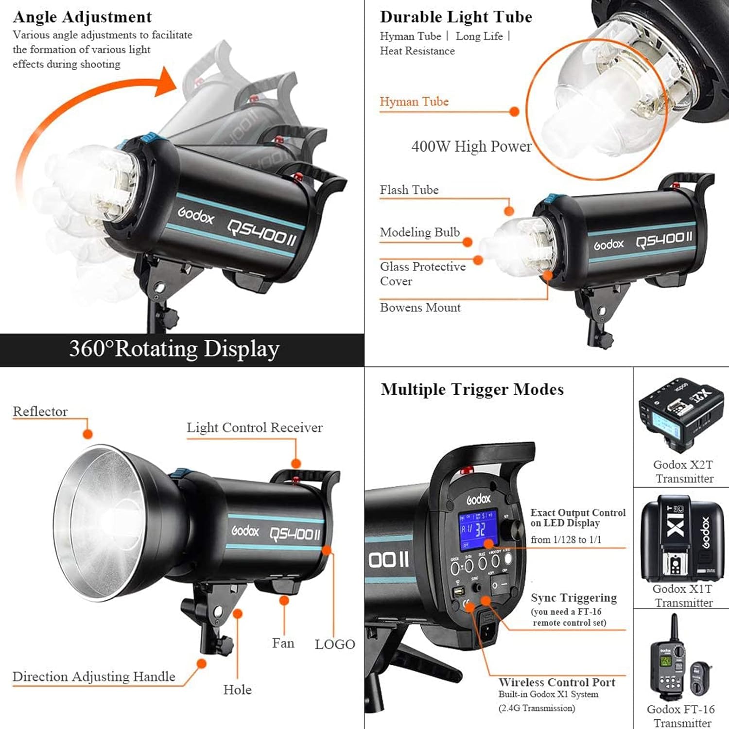
Figure 4.1: Key components and angle adjustment capabilities.

Figure 4.2: Control features and compatible wireless triggers.
4.2 Control Panel Layout
The control panel provides access to all flash functions:
- LCD Display: Shows current settings such as power output, channel, group, and mode.
- Select Dial + SET Button: Used for navigating menus and confirming selections.
- BUZZ Button: Toggles the audible flash ready indicator.
- S1/S2 Slave Model Button: Selects optical slave modes.
- Group/Channel Button: Sets wireless group and channel.
- MOD/OFF Modeling Lamp Button: Controls the modeling lamp.
- Test Button: Fires a test flash.
- Power Switch: Turns the unit on or off.
- Sync Cord Jack: For wired synchronization.
- Wireless Control Port: For connecting wireless receivers.
- AC Power Socket: Connects to mains power.

Figure 4.3: Detailed view of the control panel for easy operation.
5. Setup
5.1 Mounting the Flash Unit
- Attach the QS400II flash unit to a sturdy light stand using the mounting bracket. Ensure the bracket is securely tightened.
- Adjust the angle of the flash head using the direction adjusting handle to achieve the desired light direction.
5.2 Installing the Modeling Lamp and Glass Protective Cover
- Carefully insert the 150W modeling bulb into its socket on the flash head. Avoid touching the glass part of the bulb with bare hands.
- Place the glass protective cover over the flash tube and modeling lamp, ensuring it is securely seated.
5.3 Attaching the Standard Reflector
- Align the standard reflector with the Bowens mount on the front of the flash head.
- Twist the reflector clockwise until it clicks into place, indicating it is securely locked.
5.4 Power Connection
- Ensure the flash unit is turned off.
- Connect the power cable to the AC Power Socket on the flash unit.
- Plug the other end of the power cable into a suitable mains power outlet.
6. Operating Instructions
6.1 Power On/Off
Press the Power Switch to turn the flash unit on or off. The LCD display will illuminate upon power-on.
6.2 Adjusting Flash Output
The flash output can be adjusted in 50 steps from 1/32 to 1/1 power. Use the Select Dial to increase or decrease the power level. The current power setting is displayed on the LCD screen.
Figure 6.1: Precise power adjustment on the LCD display.
6.3 Modeling Lamp Control
Press the MOD/OFF button to toggle the 150W modeling lamp on or off. When on, the brightness can be adjusted from 5% to 100% using the Select Dial. The unit remembers the last setting after 3 seconds and recovers it upon restart.
6.4 Wireless X System (2.4G)
The QS400II features a built-in Godox 2.4G Wireless X System for remote control. This system supports 32 radio channels and 16 groups.
- Setting Channel and Group: Press the Group/Channel button and use the Select Dial to set the desired channel and group. Ensure your Godox X1, XT16, or FT-16 flash trigger is set to the same channel and group.
- Wireless Control: With a compatible trigger, you can wirelessly control flash output, modeling lamp, and buzzer functions.

Figure 6.2: Wireless control via Godox 2.4G X System.
6.5 Slave Trigger Modes (S1/S2)
The QS400II supports S1 and S2 optical slave modes, allowing it to synchronize with cameras that have a pre-flash firing system.
- S1 Mode: The flash will fire in response to the first flash from a master flash.
- S2 Mode: The flash will ignore the first pre-flash and fire in response to the second flash, suitable for cameras with pre-flash functions.
Press the S1/S2 Slave Model Button to cycle through OFF, S1, and S2 modes.
Figure 6.3: Slave trigger mode selection on the LCD.
6.6 Test Flash
Press the Test Button to fire a test flash and check the light output.
7. Maintenance
7.1 Cleaning
To clean the flash unit, use a soft, dry cloth. For stubborn dirt, a slightly damp cloth can be used, followed by a dry cloth. Do not use harsh chemicals or abrasive cleaners.
7.2 Storage
Store the flash unit in a cool, dry place, away from direct sunlight and excessive humidity. When not in use for extended periods, unplug the unit from the power source.
7.3 Lamp Replacement
If the modeling lamp or flash tube needs replacement, ensure the unit is unplugged and cooled down. Refer to the product's technical specifications for compatible replacement parts. It is recommended to have replacements performed by qualified personnel if you are unsure.
8. Troubleshooting
If you encounter issues with your Godox QS400II, refer to the following common problems and solutions:
| Problem | Possible Cause | Solution |
|---|---|---|
| Flash not firing | No power; Trigger issue; Overheat protection | Check power connection; Verify trigger settings/battery; Allow unit to cool down. |
| Modeling lamp not working | Lamp burnt out; Lamp not properly installed | Replace modeling lamp; Reinstall lamp securely. |
| Inconsistent flash output | Low power setting; Interference with wireless signal | Increase power output; Change wireless channel/group; Reduce distance to trigger. |
| Unit not turning on | Power cable loose; No power from outlet | Check power cable connection; Test outlet with another device. |
If the problem persists after attempting these solutions, please contact Godox customer support.
9. Specifications
| Feature | Specification |
|---|---|
| Model | QS400II |
| Flash Power | 400Ws |
| Guide Number (GN) | GN65 |
| Color Temperature | 5600K ± 200K |
| Recycling Time | 0.3 - 1.5 seconds |
| Flash Duration | 1/2000 - 1/800 seconds |
| Power Adjustment | 50 steps (1/32 to 1/1) |
| Modeling Lamp | 150W, 5%-100% adjustable |
| Wireless System | Built-in 2.4G Wireless X System |
| Channels/Groups | 32 Channels / 16 Groups |
| Slave Trigger Modes | OFF, S1, S2 |
| Dimensions | 19 x 9 x 11 inches |
| Manufacturer | GODOX |
| First Available Date | November 28, 2017 |
10. Warranty and Support
10.1 Warranty Information
This product is covered by a manufacturer's warranty. Please refer to the warranty card included with your product or visit the official Godox website for detailed warranty terms and conditions. Keep your purchase receipt as proof of purchase for warranty claims.
10.2 Customer Support
For technical assistance, troubleshooting, or service inquiries, please contact Godox customer support through their official website or the contact information provided in your product packaging. When contacting support, please have your product model (QS400II) and serial number ready.
Ask a question about this manual
Ask about setup, troubleshooting, compatibility, parts, safety, or missing instructions. Manuals+ will review the question and use this page’s manual context to help answer it.