1. Product Overview
This manual provides instructions for the EDGELEC 5mm Red & Green Bi-Color LED Diodes, designed for various electronic projects. This package includes 100 bi-color LEDs and 200 resistors for proper voltage regulation.
Key Features:
- Type: Bi-Color (Red & Green) LED Diodes
- Configuration: Common Cathode
- Size: 5mm Diffused Round Lens
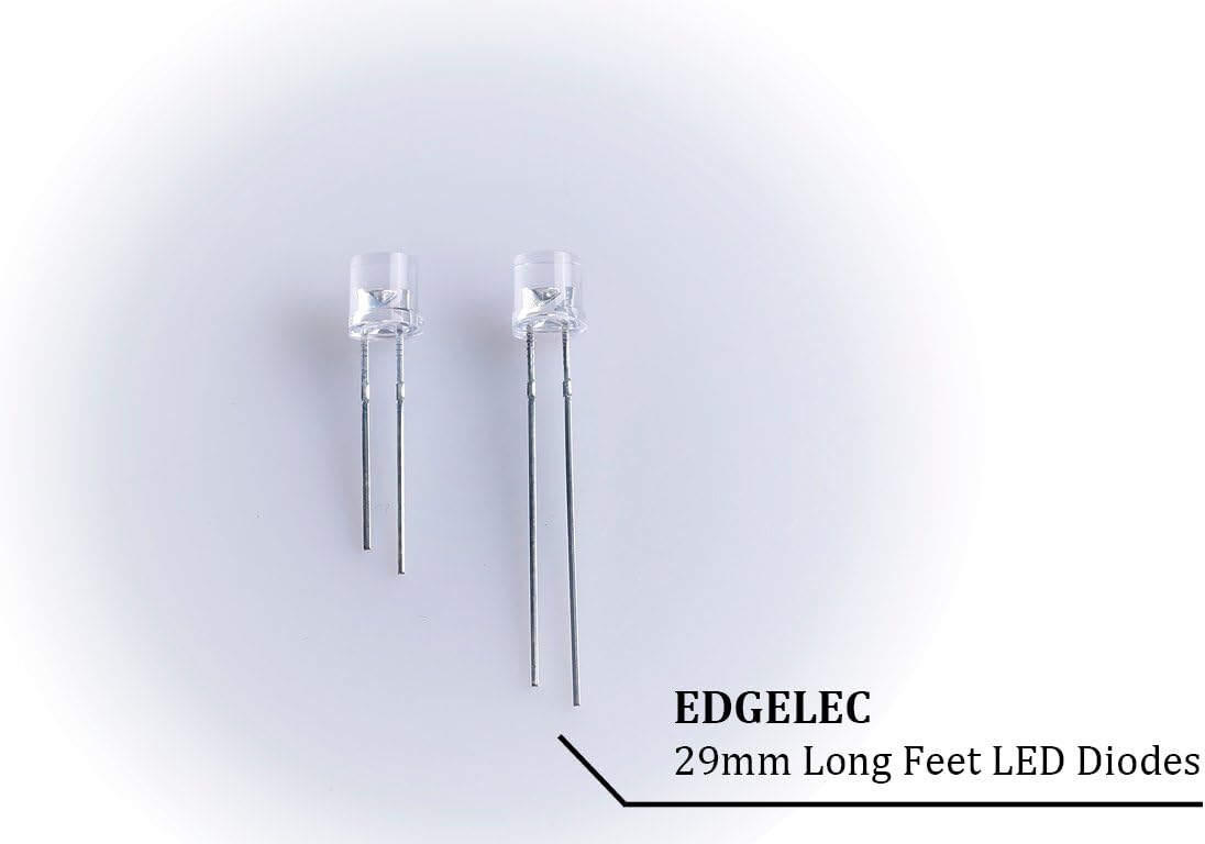
- Lead Length: 29mm for easy integration
- Included Accessories: 100pcs 430ohm resistors and 100pcs 470ohm resistors (1/4 Watt Metal Film, ±1% Tolerance) for DC 6-12V applications.
- Power Consumption: 0.06 Watts per LED.
- Viewing Angle: 120 degrees.

2. Setup and Wiring
Proper wiring is crucial for the correct operation and longevity of your LEDs. These are common cathode bi-color LEDs, meaning the negative terminal (cathode) is shared between the two colors (red and green).
Identifying Pins:
- The longest lead is the Common Cathode (-).
- The other two shorter leads are the Anodes (+) for the Red and Green colors. You may need to test to identify which anode corresponds to which color.
Connecting Resistors:
LEDs require a current-limiting resistor to prevent damage from excessive current. Connect a resistor in series with each anode (+) pin of the LED before connecting to your positive voltage source. The included resistors are suitable for DC 6-12V power supplies.
- For Red LED (Forward Voltage 2.0V): Use a 470 ohm resistor for 6-12V applications.
- For Green LED (Forward Voltage 3.0V): Use a 430 ohm resistor for 6-12V applications.
- Important: Always use a current-limiting resistor. Applying voltage directly without a resistor will damage the LED.
Wiring Diagram (Conceptual):
Connect the common cathode to the negative terminal of your power supply. Connect each anode, through its respective resistor, to the positive terminal of your power supply. To illuminate a specific color, apply voltage to its corresponding anode. To illuminate both, apply voltage to both anodes simultaneously.

3. Operating Instructions
Once properly wired with the appropriate resistors, these bi-color LEDs can be operated by applying the specified DC voltage.
- Single Color Illumination: Apply positive voltage (through a resistor) to the anode corresponding to the desired color (Red or Green). The common cathode should be connected to ground (negative).
- Mixed Color Illumination: To achieve a mixed color (e.g., orange or yellow-green), apply positive voltage (through resistors) to both the Red and Green anodes simultaneously. The resulting color will be a blend of red and green light.
- Voltage Range: The LEDs are designed for operation with DC 6-12V when used with the provided resistors.
- Current: Optimal forward current (IF) is 20mA.
4. Maintenance
These LEDs are robust and require minimal maintenance. Follow these guidelines for optimal performance and longevity:
- Storage: Store LEDs in a dry environment, away from direct sunlight, high temperatures, and excessive humidity.
- Cleaning: If necessary, gently clean the LED lens with a soft, dry cloth. Avoid abrasive materials or harsh chemicals.
- Soldering: When soldering, limit exposure to heat. For manual soldering, keep soldering time under 3 seconds at temperatures between 482°F (250°C) and 527°F (275°C). For reflow soldering, keep exposure under 5 seconds at 500°F (260°C).
5. Troubleshooting
If your LED is not functioning as expected, consider the following common issues:
- LED Not Lighting Up:
- Check power supply: Ensure the power supply is providing the correct DC voltage (6-12V).
- Verify polarity: Confirm the common cathode is connected to ground (-) and the anode(s) to the positive voltage (through resistors).
- Resistor connection: Ensure resistors are correctly wired in series with each anode. An LED without a resistor will likely burn out immediately.
- Loose connections: Check all solder joints and wire connections.
- Incorrect Color or Dim Light:
- Resistor value: Ensure the correct resistor value is used for the applied voltage. Incorrect resistor values can lead to dimness or overcurrent.
- Anode identification: Re-verify which anode corresponds to Red and which to Green.
- Damaged LED: If the LED was previously connected without a resistor or to excessive voltage, it might be damaged.
- Resistors Getting Hot:
- This can occur if the resistors are operating near their maximum power rating, especially with 12V. While the included 1/4 Watt resistors are generally suitable, for continuous operation at 12V and 20mA, consider using 1/2 Watt resistors for increased safety margin.
6. Specifications
Detailed technical specifications for the EDGELEC 5mm Red & Green Bi-Color LED Diodes:
| Parameter | Value |
|---|---|
| Brand | EDGELEC |
| Model Number | ED_YW05_R&G-C |
| LED Type | Bi-Color (Red & Green) |
| Configuration | Common Cathode |
| Lens Type | 5mm Diffused Round |
| Lead Length | 29mm |
| Forward Voltage (Red) | DC 2.0V (IF=20mA) |
| Forward Voltage (Green) | DC 3.0V (IF=20mA) |
| Power Consumption | 0.06 Watts |
| Viewing Angle | 120 Degrees |
| Included Resistors | 100x 430ohm, 100x 470ohm (1/4W, ±1%) |
| Operating Life | 25,000 Hours |
| Material | Polycarbonate (PC) |
| Item Weight | 0.36g per diode |
| UPC | 611355168910 |

7. Warranty Information
Specific warranty details for this product are not provided in the available information. Please refer to the retailer's return policy or contact EDGELEC directly for warranty inquiries.
8. Support
For further assistance or technical support, please visit the EDGELEC brand store on Amazon or contact their customer service through the platform where the product was purchased.