1. Introduction
This manual provides detailed instructions for the EDGELEC 3mm Red & Green Bi-Color LED Diodes with Common Cathode. These LEDs are designed for various electronic projects, offering low energy consumption and low heat output. Each LED features a 3mm clear round lens and a 29mm long lead for versatile applications. The package includes 200 current-limiting resistors (100x 430ohm, 100x 470ohm) suitable for DC 6-12V circuits, ensuring proper operation and longevity of the diodes.
2. Package Contents
- 100 pcs 3mm Red & Green Bi-Color LED Diodes (Common Cathode)
- 100 pcs 430ohm 1/4 Watt Metal Film Resistors (±1% Tolerance)
- 100 pcs 470ohm 1/4 Watt Metal Film Resistors (±1% Tolerance)

Image: Included 430 ohm and 470 ohm resistors, packaged separately.
3. Product Specifications
| Feature | Specification |
|---|---|
| LED Type | Bi-Color (Red & Green) |
| Configuration | Common Cathode |
| Lens Type | 3mm Clear Round Lens |
| Lead Length | 29mm |
| Forward Voltage (Red) | DC 2.0V |
| Forward Voltage (Green) | DC 3.0V |
| Forward Current (IF) | 20mA |
| Power | 0.06 Watts per LED |
| Viewing Angle | 30° |
| Included Resistors | 430ohm, 470ohm (for DC 6-12V) |

Image: Detailed electrical characteristics for various LED colors, including forward voltage, luminous intensity, and wavelength.

Image: Technical drawing illustrating the dimensions of the 3mm LED in millimeters.
4. Setup and Installation
These bi-color LEDs feature a common cathode configuration, meaning the longest lead is the common negative terminal. The other two leads control the red and green colors independently.
4.1 Identifying Leads
- Longest Lead (C): Common Cathode (connects to ground/negative).
- Shorter Lead (A): Anode for Red LED (connects to positive via resistor).
- Shorter Lead (B): Anode for Green LED (connects to positive via resistor).
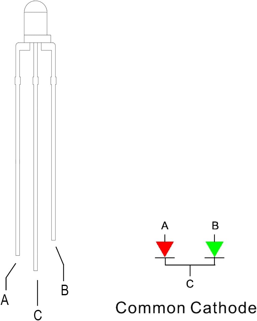
Image: Diagram illustrating the pinout of a common cathode bi-color LED, identifying the common cathode (C) and the anodes for red (A) and green (B).
4.2 Wiring with Resistors
It is crucial to use a current-limiting resistor in series with each anode (Red and Green) to prevent damage to the LED. The included 430ohm and 470ohm resistors are suitable for DC 6-12V power supplies.
- Connect the longest lead (Common Cathode) to the negative terminal of your power supply or ground.
- For the Red LED: Connect one end of a resistor (e.g., 430ohm or 470ohm) to the positive terminal of your power supply. Connect the other end of the resistor to the Red LED anode lead (A).
- For the Green LED: Connect one end of a resistor (e.g., 430ohm or 470ohm) to the positive terminal of your power supply. Connect the other end of the resistor to the Green LED anode lead (B).
Note: The specific resistor value needed depends on your supply voltage and the desired brightness. The provided resistors are general-purpose for 6-12V applications. For other voltages, calculate the appropriate resistor value using Ohm's Law: R = (Vs - Vf) / I, where Vs is supply voltage, Vf is forward voltage (2.0V for Red, 3.0V for Green), and I is desired forward current (typically 20mA or 0.02A).
5. Operating Instructions
Once wired correctly with current-limiting resistors, you can control the LED's color output:
- To light Red: Apply positive voltage (through a resistor) to the Red anode (A) while the Common Cathode (C) is connected to ground.
- To light Green: Apply positive voltage (through a resistor) to the Green anode (B) while the Common Cathode (C) is connected to ground.
- To light Yellow/Orange: Apply positive voltage (through separate resistors) to both the Red anode (A) and the Green anode (B) simultaneously. The combination of red and green light will produce a yellow or orange hue, depending on the relative brightness of each color.
Ensure your power supply voltage is within the recommended range (e.g., 6-12V when using the included resistors) and does not exceed the maximum ratings of the LED.
6. Maintenance
These LEDs are generally maintenance-free. To ensure their longevity:
- Keep the LEDs and associated components dry.
- Avoid exposing them to high temperatures, especially during soldering. Manual soldering should be less than 3 seconds at 482°F-527°F.
- Handle the leads carefully to prevent bending or breaking.
- Store in a dry environment, away from direct sunlight or extreme temperatures.
7. Troubleshooting
- LED not lighting up:
- Check polarity: Ensure the common cathode is connected to negative/ground and the anode to positive (via resistor).
- Verify power supply: Confirm the power supply is active and providing the correct voltage.
- Inspect resistor: Ensure the resistor is correctly wired and its value is not too high for the supply voltage.
- Check connections: Look for loose wires or poor solder joints.
- Test LED: A small percentage of LEDs may be faulty. Test with a known good setup.
- Incorrect color or dim light:
- Verify anode connections: Ensure the correct anode lead (A for Red, B for Green) is receiving power.
- Resistor value: If the light is too dim, the resistor value might be too high. Re-calculate or try a lower resistance (but never remove the resistor entirely).
- Voltage drop: Ensure sufficient voltage is reaching the LED after the resistor.
8. Safety Information
- Always use appropriate current-limiting resistors with LEDs to prevent overcurrent and damage.
- Do not exceed the specified forward voltage and current ratings for the LEDs.
- Avoid direct, prolonged eye exposure to the LED light, especially at high brightness.
- Keep electronic components, including these LEDs and resistors, out of reach of children.
- When soldering, ensure adequate ventilation and follow standard safety practices for handling hot tools and solder.
- These components are intended for hobbyist and educational use. Exercise caution and proper electrical safety practices.
9. Warranty and Support
EDGELEC products are manufactured to high standards. For technical support, product inquiries, or information regarding potential warranties, please refer to the manufacturer's official website or contact their customer service directly. Please have your product model number (ED_YT03_R&G-C_100Pcs) available when seeking support.