1. Product Overview
The HiLetgo ESP32 ESP-WROOM-32 is a versatile WiFi and Bluetooth wireless board module, featuring a powerful ESP32 dual-core CPU. This development board is designed for a wide range of IoT applications, offering integrated lithium battery charging capabilities and a compact form factor. It provides robust connectivity and processing power for your projects.

Figure 1: HiLetgo ESP32 ESP-WROOM-32 Development Board
2. Package Contents
Please verify that all items are present in your package:
- 1 x HiLetgo ESP32 ESP-WROOM-32 Board
- 1 x 16-pin Header
- 1 x 20-pin Header
3. Specifications
| Feature | Detail |
|---|---|
| Chip | ESP32-32 (ESP-WROOM-32 module) |
| Working Voltage | 3.3V |
| CPU Model | Dual Core (Espressif) |
| Maximum Computing Speed | 240MHz |
| RAM Memory Installed Size | 4 MB (LPDDR4) |
| Storage Capacity | 4 MBytes Flash |
| Connectivity Technology | Wi-Fi (802.11 b/g/n), Bluetooth |
| USB Chip | CP2104 |
| Connection Interface | Micro-USB |
| GPIO Pins | 28 total (26 Digital I/O, 12 Analog I/O) |
| Power Plug | PH-2 2.0mm (for LiPo battery) |
| Max Charging Current | 500mA |
| Operating System | FreeRTOS |
| Dimensions (L x W x H) | 57mm x 25mm x 14mm (2.24"L x 0.98"W x 0.55"H) |
| Weight | 8g |
| Model Number | 3-01-1483 |
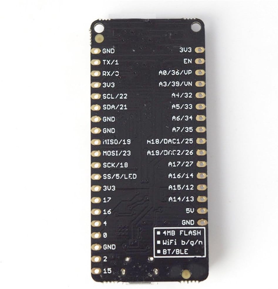
Figure 2: ESP32 Board Pinout Diagram
4. Setup Guide
4.1 Initial Inspection
Before proceeding, carefully inspect the ESP32 board for any visible damage. Ensure all components are securely attached.
4.2 Driver Installation
The board uses a CP2104 USB-to-UART bridge chip. You may need to install the appropriate drivers for your operating system (Windows, macOS, Linux) to allow your computer to communicate with the board. Drivers can typically be found on the Silicon Labs website or through a quick online search for "CP2104 driver".
4.3 Integrated Development Environment (IDE) Setup
The ESP32 board is compatible with popular development environments such as the Arduino IDE and PlatformIO. Follow the instructions for your chosen IDE to add ESP32 board support:
- Arduino IDE: Install the ESP32 board package via the Boards Manager.
- PlatformIO: Add the Espressif 32 platform to your project.
4.4 Connecting the Board
Connect the ESP32 board to your computer using a Micro-USB cable. The board should be recognized by your system after driver installation.

Figure 3: ESP32 Board on a Breadboard
4.5 Powering the Board
The board can be powered via the Micro-USB port or a 3.7V Lithium Polymer (LiPo) battery connected to the PH-2 2.0mm connector.
Important Battery Polarity Warning: The PH-2 2.0mm battery connector on this board may have reversed polarity compared to some standard LiPo battery connectors. Before connecting any battery, carefully verify that the positive (+) terminal on your battery aligns with the positive (+) marking on the board, and the negative (-) terminal aligns with the negative (-) marking. Connecting a battery with reversed polarity can permanently damage the board. If necessary, carefully swap the wires in your battery connector to match the board's polarity.

Figure 4: ESP32 Board with USB and Battery Power
4.6 Uploading Code (Programming Mode)
To reliably upload sketches to the ESP32 board, you typically need to put it into programming mode:
- Connect the board to your computer via Micro-USB.
- Press and hold the BOOT button (often labeled as GPIO 0 or similar).
- While holding BOOT, press and release the RESET button.
- Release the BOOT button. The board is now in download mode.
- Initiate the code upload from your IDE.
- Once the upload is complete, press the RESET button again to run your new sketch.
For more consistent uploads, some users have found success by adding a small capacitor (e.g., 10uF) between the GND and EN pins.
5. Operating Instructions
5.1 Basic Operation
Once your code is uploaded, the ESP32 will execute it upon reset or power-up. You can monitor serial output via the Serial Monitor in your IDE (typically at 115200 baud).
5.2 Serial Communication
The ESP32 features three hardware serial ports:
- U0UXD: Used for communication with the ESP32 during programming and boot. This is the default
Serialobject in Arduino. - U1UXD: Available for your projects. Note that some boards might use this for SPI Flash access.
- U2UXD: Available for your projects.
When using additional serial ports (U1UXD, U2UXD), it is recommended to use HardwareSerial instead of SoftwareSerial for better performance and reliability. An example for Serial2:
#include <HardwareSerial.h>
#define RXD2 16 // Rx pin GPIO 16
#define TXD2 17 // Tx pin GPIO 17

void setup() {
  Serial.begin(115200);
  Serial2.begin(9600, SERIAL_8N1, RXD2, TXD2);
  Serial.println("Serial Txd is on pin: " + String(TXD2));
  Serial.println("Serial Rxd is on pin: " + String(RXD2));
}

void loop() {
  while (Serial2.available()) {
    Serial.print(char(Serial2.read()));
  }
}
5.3 Power Management (Deep Sleep)
For battery-powered applications, the ESP32 supports various low-power modes, including Deep Sleep. Implementing Deep Sleep can significantly extend battery life. Refer to the ESP-IDF documentation or Arduino ESP32 examples for detailed guidance on using esp_deep_sleep_start() and other power-saving functions.
6. Maintenance
6.1 Handling Precautions
- Avoid touching the board's components unnecessarily, especially when powered.
- Handle the board by its edges to prevent electrostatic discharge (ESD) damage.
- Do not apply excessive force when connecting cables or components.
6.2 Storage
Store the board in an anti-static bag in a cool, dry environment when not in use. Avoid extreme temperatures and humidity.
6.3 Cleaning
If cleaning is necessary, use a soft, dry brush or compressed air to remove dust. For stubborn grime, use isopropyl alcohol with a cotton swab, ensuring the board is unpowered and completely dry before re-applying power.
7. Troubleshooting
7.1 Board Not Powering On
- Check USB Connection: Ensure the Micro-USB cable is securely connected to both the board and your computer/power source. Try a different USB cable or port.
- Verify Battery Polarity: If using a LiPo battery, double-check that the polarity of the PH-2 2.0mm connector matches the board's markings. Reversed polarity will prevent the board from powering on and can cause damage.
- Power Source: Ensure your USB port or external power supply provides sufficient current (e.g., 5V, 500mA or more).
7.2 Code Upload Issues
- Programming Mode: Ensure the board is correctly put into programming mode (GPIO 0 held low, then RESET, then release GPIO 0) before initiating the upload.
- Driver Issues: Confirm that the CP2104 USB-to-UART drivers are correctly installed and the board is recognized as a COM port in your device manager.
- IDE Settings: Verify that the correct board (e.g., "ESP32 Dev Module") and COM port are selected in your IDE.
- Serial Monitor Interference: Close the Serial Monitor in your IDE before uploading, as it can sometimes interfere with the upload process.
- Capacitor for Stability: If uploads are consistently unreliable, consider adding a small capacitor (e.g., 10uF) between the GND and EN pins to stabilize the boot sequence.
7.3 Wi-Fi/Bluetooth Connectivity Problems
- Code Verification: Double-check your Wi-Fi credentials (SSID, password) and Bluetooth code for errors.
- Antenna: Ensure the onboard antenna is not obstructed and the board is within range of your Wi-Fi access point or Bluetooth device.
- Power Supply: Insufficient power can lead to unstable wireless communication.
7.4 Board Becomes Unresponsive
- Hard Reset: Disconnect all power sources (USB and battery), wait a few seconds, then reconnect.
- Re-upload Firmware: If the board is still unresponsive, try re-uploading a known working sketch (e.g., a simple blink example) to rule out software issues.
8. Warranty Information
HiLetgo products are typically covered by a limited warranty against manufacturing defects. Please retain your proof of purchase. For specific warranty terms and conditions, refer to the documentation provided at the time of purchase or contact HiLetgo customer support.
9. Customer Support
If you encounter issues not covered in this manual or require further assistance, please contact HiLetgo customer support through their official website or the platform where you purchased the product. Provide your product model number (3-01-1483) and a detailed description of the problem for efficient support.