
1. Introduction
This manual provides detailed instructions for the assembly, installation, operation, and maintenance of your Five Star Outdoor 4K HDTV Antenna. This antenna is designed to receive digital television (DTV), VHF, UHF, and FM radio signals, offering high-definition reception with a motorized 360-degree rotation feature and an infrared remote control. It includes an Auto Gain Control amplifier and an LTE filter for enhanced signal quality.
2. Safety Information
- Electrical Safety: Always exercise caution when working with electrical components. Ensure all power is disconnected before making any connections.
- Outdoor Installation: When installing the antenna outdoors, avoid contact with power lines, utility wires, or other electrical hazards. Use a sturdy ladder and ensure stable footing.
- Mounting Stability: Securely mount the antenna to prevent it from falling due to wind or other environmental factors. Use appropriate mounting hardware for your chosen surface.
- Weather Conditions: Avoid installation during adverse weather conditions such as strong winds, rain, or lightning.
- Cable Management: Route coaxial cables safely to prevent tripping hazards and protect them from damage.
3. Package Contents
Verify that all components are present before beginning assembly:
- Five Star Outdoor HDTV Antenna Unit
- Motorized Rotator Base
- Infrared Remote Control
- Control Box (Power Supply/Signal Amplifier)
- J-Pole Mounting Kit
- 40ft Coaxial Cable
- 4-way Coaxial Splitter
- 15pcs Cable Clips
- Power Adapter for Control Box

Image 3.1: Main components including the antenna, control box, and remote control.
4. Assembly Instructions
Follow these steps to assemble your Five Star Outdoor HDTV Antenna:
- Unpack Components: Carefully remove all parts from the packaging.
- Assemble Antenna Elements: Attach the various antenna elements (VHF and UHF) to the main boom of the antenna. Ensure they are securely fastened according to the diagrams. The antenna features additional UHF elements and larger VHF elements for improved reception.
- Attach Reflector Panels: Secure the reflector panels to the rear of the antenna structure. These panels enhance signal gain.
- Connect Motorized Base: Attach the motorized rotator base to the main antenna assembly. Ensure the connection is firm.
- Connect Coaxial Cable to Antenna: Connect one end of the coaxial cable to the F-connector on the motorized base of the antenna. Ensure the connection is finger-tight, but do not overtighten. Leave enough slack in the cable near the rotator to allow for 360-degree rotation without strain.

Image 4.1: View of the antenna elements and their assembly onto the main boom.
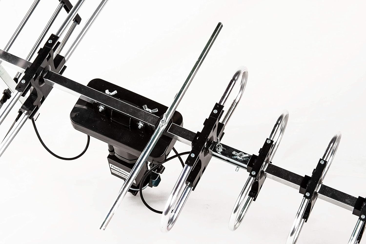
Image 4.2: Detailed view of how antenna elements are secured.

Image 4.3: The F-connector on the antenna base where the coaxial cable connects.

Image 4.4: The motorized base of the antenna, illustrating the 360-degree rotation capability. Note the caution regarding cable slack for rotation.
5. Installation Guide
Proper installation is crucial for optimal signal reception.
- Mount the J-Pole: Secure the J-Pole to a stable outdoor surface, such as a roof, wall, or mast, ensuring it is vertical and robust enough to support the antenna in all weather conditions.
- Attach Antenna to J-Pole: Mount the assembled antenna onto the J-Pole using the provided clamps and hardware. Ensure it is tightly secured.
- Route Coaxial Cable: Carefully route the 40ft coaxial cable from the antenna to the location of your TV(s) and the control box. Use the provided cable clips to secure the cable and prevent damage.
- Connect to Control Box: Connect the coaxial cable from the antenna to the 'ANT IN' port on the control box.
- Connect to TV(s):
- For one TV: Connect a coaxial cable from the 'TV1' or 'RF IN/TV2' port on the control box directly to the 'Antenna In' or 'RF In' port on your television.
- For two TVs: Use the provided 4-way coaxial splitter. Connect a short coaxial cable from the 'TV1' or 'RF IN/TV2' port on the control box to the input of the splitter. Then, connect two separate coaxial cables from the splitter's outputs to the 'Antenna In' or 'RF In' ports on each of your two televisions.
- Power the Control Box: Plug the power adapter into the 'AC IN' port on the control box, then plug the adapter into a standard electrical outlet. The power indicator light on the control box should illuminate.

Image 5.1: Diagram illustrating how to connect the antenna to the control box and then to one or two televisions.
6. Operating Instructions
Once installed, follow these steps to operate your antenna:
- Power On: Ensure the control box is powered on. The power LED should be lit.
- Select TV Input: On your television, select the correct input source (e.g., 'Antenna', 'TV', 'Air') to receive over-the-air broadcasts.
- Scan for Channels: Access your TV's menu and navigate to the 'Channel Scan' or 'Auto Program' function. Initiate a full channel scan. This process may take several minutes.
- Adjust Antenna Direction: Use the infrared remote control to rotate the antenna. Point the remote at the control box and press the 'Control' button. The antenna will rotate 360 degrees. Observe your TV screen for signal strength and picture quality as the antenna rotates. Stop rotation when you achieve the best possible reception for your desired channels. You may need to perform multiple scans at different antenna orientations to find all available channels.
- Auto Gain Control: The built-in Auto Gain Control (AGC) automatically adjusts the signal amplification (15-35db) to optimize reception, preventing signal overload in strong signal areas and boosting weak signals in distant areas.
- LTE Filter: The integrated LTE filter helps to reduce interference from 4G/5G cellular signals, ensuring clearer digital TV reception.

Image 6.1: The control box and its infrared remote control, used for rotating the antenna and managing signal.

Image 6.2: Internal view of the control box highlighting the smart chip, AGC, LTE filter, and support for 4K DTV/VHF/UHF signals.
7. Maintenance
To ensure long-term performance of your outdoor antenna:
- Periodic Inspection: Annually inspect the antenna, mounting hardware, and coaxial cables for any signs of wear, corrosion, or damage.
- Cleanliness: Gently clean the antenna elements if they accumulate excessive dirt, dust, or debris, which can affect signal reception. Use a soft cloth and mild detergent if necessary.
- Cable Integrity: Check coaxial cable connections for tightness and ensure the cable jacket is intact to prevent water ingress.
- Wind Resistance: The antenna is designed with special wind-proof features, but ensure it remains securely mounted after severe weather.
8. Troubleshooting
If you experience issues with your antenna, refer to the following common problems and solutions:
| Problem | Possible Cause | Solution |
|---|---|---|
| No signal or poor picture quality | Incorrect TV input, loose cable connections, antenna not aimed correctly, interference, TV not scanned for channels. | Ensure TV input is 'Antenna/Air'. Check all coaxial cable connections. Use the remote to rotate the antenna and rescan for channels at different orientations. Check for local interference sources. |
| Antenna rotation not working | Control box not powered, remote control battery low, remote not aimed at control box, cable snag. | Verify control box power. Replace remote batteries. Ensure direct line of sight between remote and control box. Check for any obstructions or tight cables preventing rotation. |
| Fewer channels than expected | Antenna not optimally aimed, incomplete channel scan, geographical limitations. | Perform multiple channel scans after rotating the antenna to different directions. Consult online resources for local broadcast tower locations to aid in aiming. |
| Intermittent signal loss | Weather conditions, nearby obstructions (e.g., trees, buildings), loose connections. | Check all connections. Consider antenna relocation if obstructions are significant. Signal can be affected by severe weather. |
9. Specifications
| Feature | Detail |
|---|---|
| Model Number | FSA-1806NK |
| Product Dimensions | 17 x 8 x 7 inches |
| Item Weight | 4.97 pounds |
| Antenna Type | Outdoor, Directional, Motorized |
| Frequency Range | 45-860MHz (UHF/VHF/FM) |
| Gain | 15-35dB (Auto Gain Control) |
| Impedance | 75 Ohm |
| Rotation | 360 Degree Motorized with Infrared Remote Control |
| Supported Resolutions | 4K HD TV, 1080p, 1080i, 720p |
| Number of Channels | Up to 100+ local channels (dependent on location) |
| UPC | 840449111000 |
10. Warranty and Support
For warranty information, technical support, or customer service inquiries, please refer to the manufacturer's official website or contact their customer support directly. Keep your purchase receipt as proof of purchase.