1. Introduction
This manual provides detailed instructions for the installation, operation, and maintenance of your UHPPOTE 600lb Outswinging Electric Magnetic Door Lock Kit with RF Remote Control. Please read this manual thoroughly before installation and use to ensure proper function and safety. This system is designed to provide secure access control for outswinging doors, offering convenience through remote operation.
2. Package Contents
Verify that all components listed below are included in your package:
- Electromagnetic Lock (600lbs holding force)
- RF Remote Control Receiver (HBK-R01)
- RF Remote Control Transmitter (2 units)
- Exit Button
- Power Adapter

Figure 1: Complete Kit Components
3. Specifications
| Component | Specification |
| Electromagnetic Lock Holding Force | 600lbs (280kg) |
| Electromagnetic Lock Input Voltage | 12VDC |
| Electromagnetic Lock Current | 520mA |
| Electromagnetic Lock Mode | Fail-Safe (Unlocked while power is removed) |
| Electromagnetic Lock Dimensions (LxWxH) | 9-27/32" x 1-59/64" x 1-3/32" (250x48.8x27.9mm) |
| Armature Plate Dimensions (LxWxH) | 7-3/32" x 1-17/32" x 33/64" (180x38.8x13mm) |
| Remote Transmitter Working Voltage | 6VDC |
| Remote Transmitter Operating Current | 3mA |
| Remote Transmitter Battery | 2x CR2016/3V (Built-in) |
| Remote Transmitter Frequency | 433.92MHZ |
| Remote Transmitter Buttons | 1 |
| Remote Transmitter Enclosure Material | ABS Plastic |
4. Installation
Follow these steps to install your access control system. Ensure power is disconnected before beginning installation.
4.1 Component Overview

Figure 2: Electromagnetic Lock
The electromagnetic lock consists of a main magnet unit and an armature plate. The main unit is typically mounted on the door frame, and the armature plate is mounted on the door.
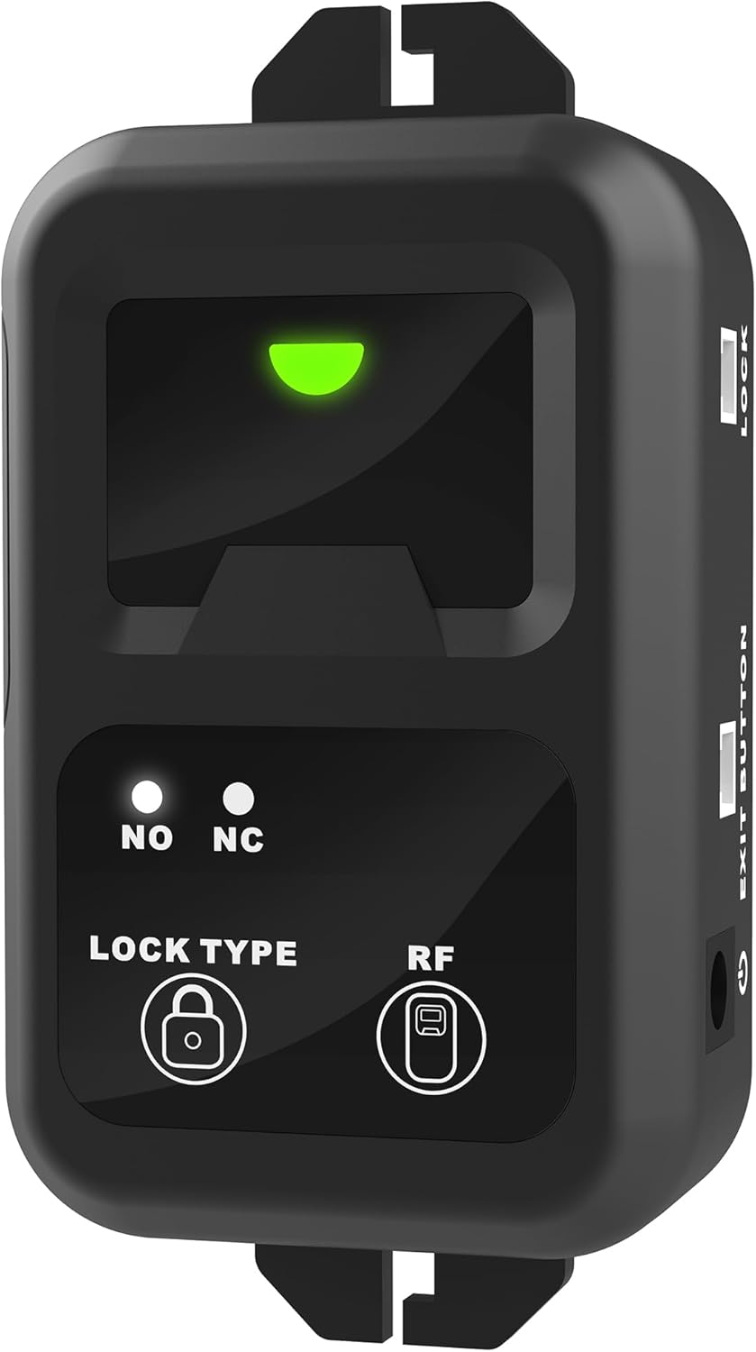
Figure 3: Remote Control Receiver (HBK-R01)
The remote control receiver manages the lock's operation based on signals from the remote transmitter and the exit button. It features indicator lights for status and buttons for lock type and RF pairing.
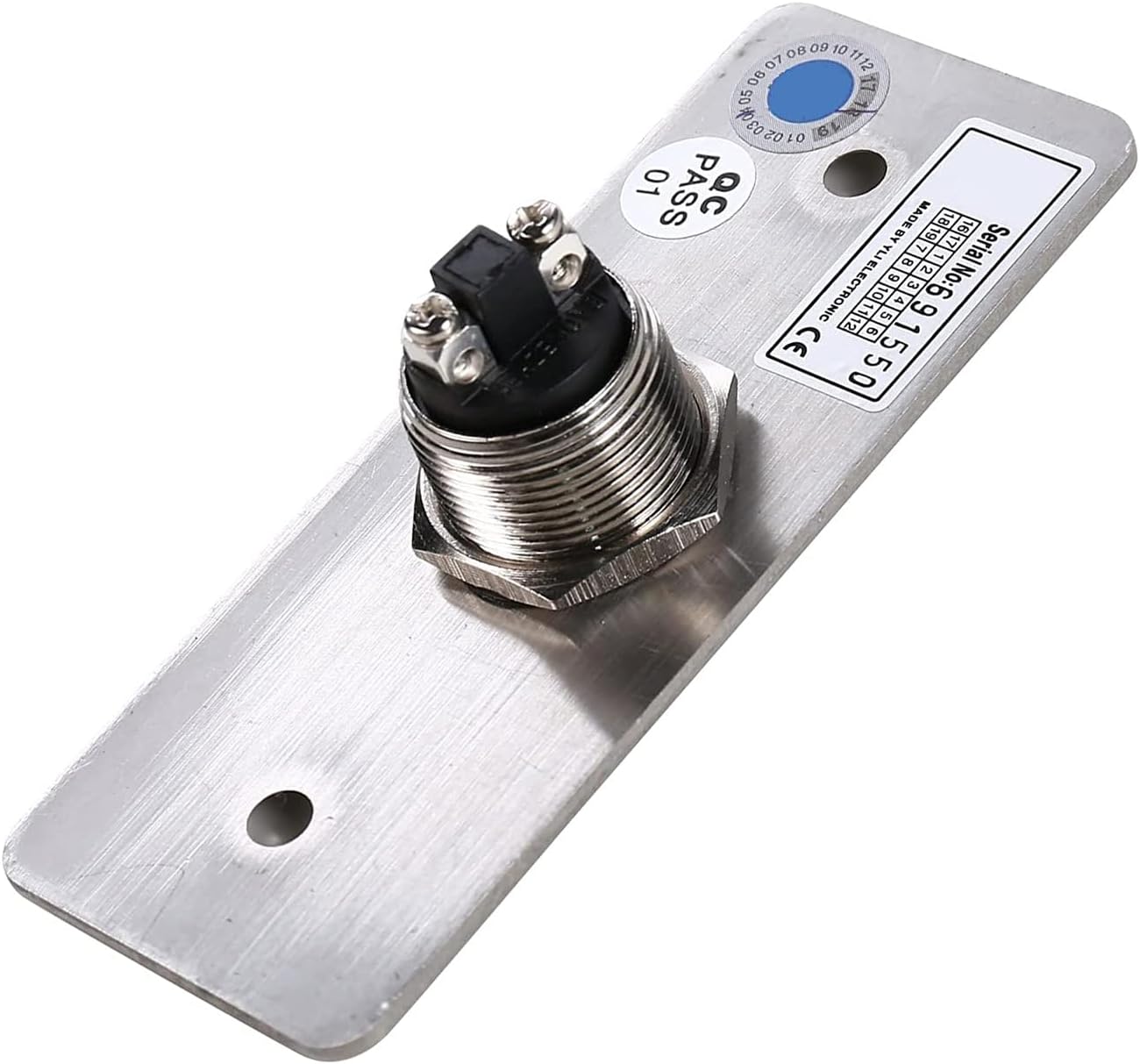
Figure 4: Exit Button
The exit button provides a manual release for the lock from the inside.

Figure 5: Power Adapter
The power adapter supplies 12VDC power to the system.
4.2 Wiring Diagram
Refer to the following diagram for proper wiring connections between the components.

Figure 6: Wiring Demonstration Diagram
4.3 Wiring Videos
For visual guidance on wiring, please watch the official videos below:
Wiring Video (Access Keypad + HBK-R01 + HBK-P02)
This video demonstrates the wiring process for connecting an access keypad, the HBK-R01 remote receiver, and the HBK-P02 power supply.
Wiring Video (Access Keypad + HBK-R01 + Power Adapter)
This video illustrates how to connect an access keypad, the HBK-R01 remote receiver, and a power adapter.
Wiring Video (HBK-R01 + Electromagnetic Lock)
This video shows the wiring connections between the HBK-R01 remote receiver and the electromagnetic lock.
5. Operating Instructions
5.1 Remote Control Operation
The system allows you to open the door by pressing the wireless RF remote control. The remote communicates with the receiver, which can program up to 40 remotes and has a range of 164 feet.

Figure 7: RF Remote Control Transmitter
The remote control receiver (HBK-R01) has a built-in buzzer that indicates the status of the lock (open or locked).
Operating Video of Remote Control HBK-R01
This video demonstrates the operation of the HBK-R01 remote control receiver, including pairing and function settings.
5.2 Exit Button Operation
An exit button is included in this magnetic lock system kit. You can exit from indoors easily by pushing it once. The exit button will momentarily release the lock.
6. Maintenance
- Regularly inspect all wiring connections to ensure they are secure and free from damage.
- Keep the electromagnetic lock and armature plate clean and free of debris to ensure optimal contact and holding force.
- Check the remote control transmitter batteries periodically. The remote uses 2x CR2016/3V batteries.
7. Troubleshooting
7.1 Weak Holding Force
If the electromagnetic lock exhibits weak holding force, ensure the armature plate is not installed too tightly. Loosen the armature plate screws slightly to allow for proper alignment and full contact with the magnet unit. This ensures the full 600lb holding force can be achieved.
7.2 Remote Control Not Responding
- Check the batteries in the remote control transmitter. Replace if necessary.
- Ensure the remote control receiver is powered on and its indicator light is active.
- Re-pair the remote control transmitter with the receiver. Refer to the 'Operating Video of Remote Control HBK-R01' in Section 5.1 for pairing instructions.
- Verify that the remote control is within the 164-foot operating range of the receiver.
7.3 Lock Not Engaging/Disengaging
- Check all wiring connections for the electromagnetic lock and the remote receiver. Ensure they are correctly connected according to the wiring diagram (Figure 6) and the wiring videos in Section 4.3.
- Confirm that the power adapter is securely plugged into a working outlet and providing power to the system.
- For fail-safe locks, ensure continuous power supply. If power is interrupted, the lock will disengage.
8. Warranty and Support
For warranty information or technical support, please contact UHPPOTE directly through their official channels or the retailer from whom the product was purchased. Keep your purchase receipt as proof of purchase.


