
1. Introduction
The Walfront 0.01-4GHz 21dB Wideband LNA Amplifier Module (Model: Walfronturyea238on) is a high-gain, low-noise amplifier designed for various radio frequency applications, including HAM radio, RTL SDR, and general broadband signal amplification. This module features a robust design with immersion gold processing for enhanced reliability and performance. This manual provides essential information for the proper setup, operation, and maintenance of your LNA module.

Figure 1.1: Walfront 0.01-4GHz 21dB Wideband LNA Amplifier Module with attached red antennas.
2. Safety Information
Please read and understand all safety instructions before using this product. Failure to follow these instructions may result in electric shock, fire, or damage to the product.
- Power Supply: Use only a stable +5V DC power supply. Exceeding the recommended voltage may damage the module.
- Electrostatic Discharge (ESD): Handle the module with care to prevent damage from electrostatic discharge. Use ESD precautions such as grounding straps when handling.
- Environment: Do not expose the module to moisture, extreme temperatures, or corrosive environments.
- Modifications: Do not attempt to modify or disassemble the module. Unauthorized modifications will void the warranty and may cause damage.
- Professional Use: This product is intended for users with knowledge of RF electronics. If you are unsure about any aspect of its use, consult a qualified professional.
3. Package Contents
Verify that all items are present and in good condition upon opening the package.
- 1 x Walfront 0.01-4GHz 21dB Wideband LNA Amplifier Module
4. Key Features
The Walfront LNA Amplifier Module offers the following features:
- Immersion Gold Process: Double-sided printed circuit board with immersion gold finish ensures stable color, brightness, smooth coating, and good welding properties, enhancing reliability and corrosion resistance.
- Wide Bandwidth: Operates across an ultra-wide frequency range of 0.01-4GHz, suitable for diverse applications.
- High Gain: Provides a typical gain of 21dB at 1.9GHz.
- Low Noise: Features a low noise coefficient of 1.3dB, improving signal clarity.
- High Output Power: Maximum output power (P1dB) of +22dBm typical, with +39.5 dBm Output IP3.
- Stable Operation: Unconditionally stable performance with inductors and capacitors designed without resonant points.
- Compact Design: Small form factor (32 x 23mm) for easy integration into existing setups.

Figure 4.1: Illustration showing the minor differences between new and old production models of the amplifier module. Both types offer identical functionality.
5. Technical Specifications
| Parameter | Value |
|---|---|
| Bandwidth | 0.01 - 4 GHz |
| Noise Coefficient | 1.3 dB |
| Power Supply Voltage | +5V DC (Typical) |
| Supply Current | 125 mA (Typical) |
| Gain | 21 dB @ 1.9 GHz (Typical) |
| Input/Output Impedance | 50 Ω |
| Maximum Output Power (P1dB) | +22 dBm (Typical) |
| Output IP3 | +39.5 dBm |
| Dimensions | 32 x 23 mm (1.26 x 0.91 inch) |
| Weight | 5 g |
| Material | Gold (Immersion Gold Process) |
| Mounting Type | Surface Mount |
| Number of Channels | 1 |

Figure 5.1: Physical dimensions of the LNA module, measuring approximately 32mm by 23mm.
6. Setup Instructions
Follow these steps to properly set up your Walfront LNA Amplifier Module:
- Prepare Workspace: Ensure your workspace is clean, well-lit, and free of static electricity. Use an anti-static mat and wrist strap if available.
- Identify Connections: Locate the RF_IN, RF_OUT, and +5V power input terminals on the module. The module typically uses SMA connectors for RF input and output, and solder pads for power.
- Connect RF Input: Connect your signal source (e.g., antenna, pre-amplifier output) to the RF_IN port using a 50 Ω coaxial cable with appropriate SMA connectors.
- Connect RF Output: Connect the RF_OUT port to your receiver, SDR, or subsequent RF stage using a 50 Ω coaxial cable with appropriate SMA connectors.
- Apply Power: Connect a stable +5V DC power supply to the +5V and GND (ground) pads. Ensure correct polarity. The module typically draws 125mA.
- Note: The module is designed for a typical +5V supply. Verify your power source provides a clean, regulated +5V DC.
- Verify Connections: Double-check all connections for proper seating and polarity before applying power.
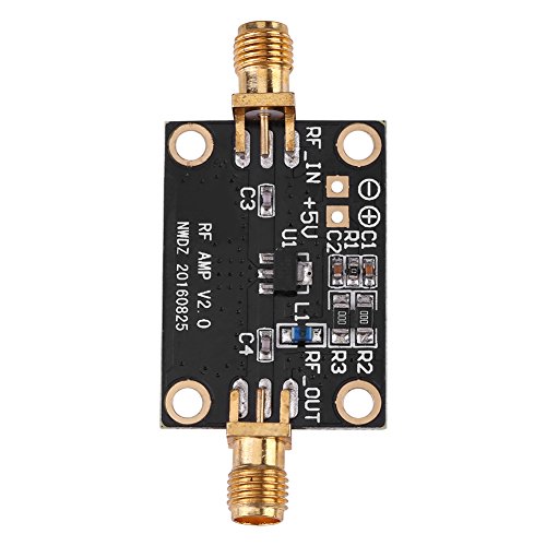
Figure 6.1: Top view of the LNA module, highlighting the RF input, RF output, and +5V power connection points.
7. Operating Instructions
Once the module is correctly set up, follow these guidelines for operation:
- Power On: Apply the +5V DC power to the module. The module will immediately become active.
- Signal Flow: The LNA will amplify the signal received at the RF_IN port and output the amplified signal at the RF_OUT port.
- Frequency Range: The amplifier is designed for optimal performance within the 0.01-4GHz bandwidth. Performance may vary slightly at the extreme ends of this range.
- Input Power: Ensure that the input signal power does not exceed the module's maximum input power capability to prevent damage. The module has high input power capability, but excessive power can still cause saturation or damage.
- Monitoring: Monitor the output signal on your connected receiver or spectrum analyzer to ensure proper amplification and signal quality.
Note: This LNA is designed to improve the signal-to-noise ratio of weak signals. It is generally placed as close as possible to the antenna or signal source to minimize noise pickup in the signal path before amplification.
8. Maintenance
The Walfront LNA Amplifier Module requires minimal maintenance. Follow these recommendations to ensure its longevity:
- Cleaning: Keep the module clean and free of dust and debris. Use a soft, dry cloth for cleaning. Do not use liquid cleaners or solvents.
- Storage: When not in use, store the module in a dry, cool, and static-free environment.
- Inspection: Periodically inspect the module for any signs of physical damage, loose connections, or corrosion.
9. Troubleshooting
If you encounter issues with your LNA module, refer to the following troubleshooting guide:
| Problem | Possible Cause | Solution |
|---|---|---|
| No signal amplification or weak output. | Incorrect power supply voltage or polarity. Loose or incorrect RF connections. Damaged module. Input signal too weak or out of frequency range. | Verify power supply is a stable +5V DC and polarity is correct. Check all RF_IN and RF_OUT connections for proper seating. Inspect the module for visible damage. If damaged, replace. Ensure input signal is within 0.01-4GHz and strong enough for detection. |
| Excessive noise or distortion in output. | Poor grounding. Interference from other electronic devices. Over-driving the input with too strong a signal. | Ensure proper grounding of your entire RF system. Relocate the module away from potential interference sources. Reduce the input signal level if it is too high. |
| Module not powering on (no activity). | No power supply. Faulty power supply or cable. Incorrect power connection. | Confirm power supply is connected and switched on. Test power supply with a multimeter. Try a different power supply. Double-check +5V and GND connections for correct polarity. |
10. Warranty and Support
Walfront products are designed for reliability and performance. While specific warranty details are not provided in this manual, please retain your proof of purchase for any warranty claims.
For technical support, product inquiries, or warranty information, please contact your retailer or visit the official Walfront website. Provide your product model number (Walfronturyea238on) and purchase details when seeking assistance.
Walfront Official Store: https://www.amazon.com/stores/Walfront/page/FECAC109-E5D3-4C74-B6F1-3FA643B2EA7D