1. Introduction
This manual provides essential information for the safe and effective use of the Vannamore 3LO1I Mini Cathode Ray Tube (CRT). The 3LO1I is a compact CRT designed for visual monitoring of electronic processes, featuring electrostatic focus and deflection, a round screen, and green phosphor with average persistence.
It is primarily intended for integration into various radio and technical devices where visual observation of waveforms or data is required.
2. Product Overview
The 3LO1I is a specialized vacuum tube that generates and displays electron beams. Its design allows for precise control of the electron beam's position and focus, enabling the visualization of electrical signals.
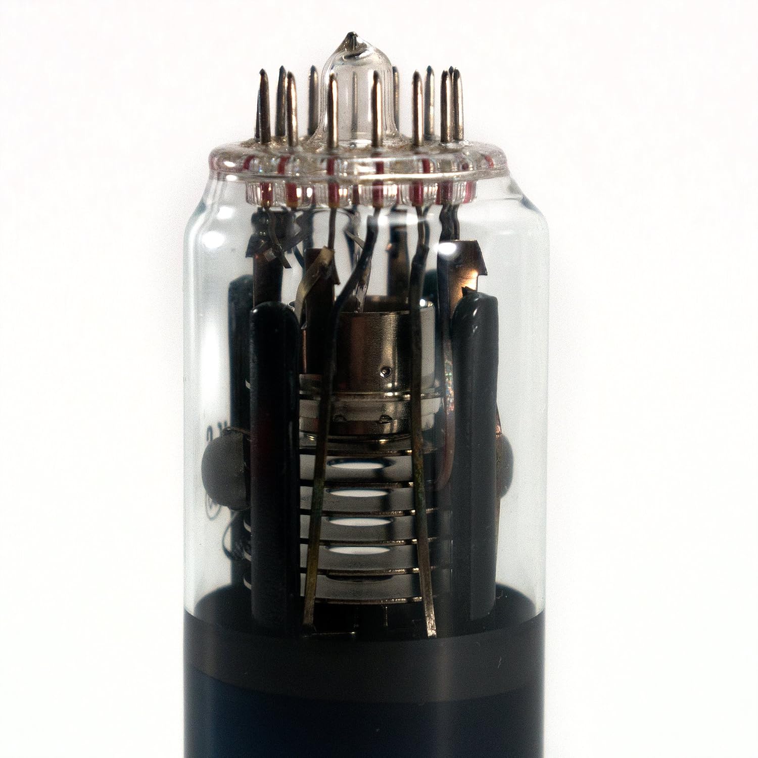
Figure 2.1: Side view of the 3LO1I Mini CRT, showing its glass envelope and internal components.
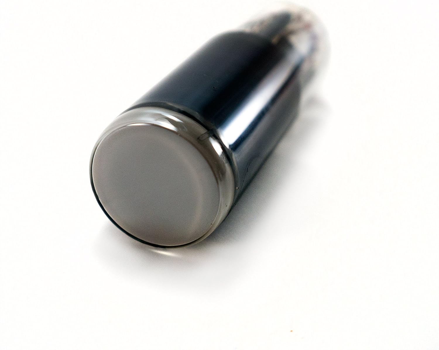
Figure 2.2: Angled view of the 3LO1I Mini CRT, highlighting the screen end and the base pins.

Figure 2.3: Close-up view of the 3LO1I Mini CRT's base pins, essential for electrical connections.
3. Technical Specifications
The following table details the basic and maximum operational values for the 3LO1I Mini CRT.
| Parameter | Basic Technical Specifications | Maximum Operational Values |
|---|---|---|
| Heater Voltage | 6.3V | 5.7V - 6.9V |
| Heater Current | 0.54 - 0.66A | N/A |
| 2nd Anode Voltage | 500V | 500V - 800V |
| 1st Anode Voltage (Best Focus) | 0 - 50V | Max 150V |
| Cut-off Voltage | -90V - -30V | N/A |
| Control Grid Voltage | N/A | -125V - 0V |
| Heater-Cathode Voltage | N/A | -125V - 0V |
| Impedance in Control Grid Circuit | N/A | No more than 1.5MΩ |
| Impedance in Deflection Plate Circuit (50Hz) | N/A | No more than 2MΩ |
| Voltage between Deflection Plates and 2nd Anode | N/A | -450V - 450V |
| Diameter of Tube | No more than 33.5mm | N/A |
| Length of Tube | No more than 115mm | N/A |
Important Note: Operation of the CRT with two or more simultaneous maximum values is not permitted. Exceeding these limits can damage the tube.
4. Pinout and Connections
Proper connection of the 3LO1I CRT is crucial for its functionality and safety. Refer to the diagram below for pin assignments and dimensions.

Figure 4.1: Pinout diagram (bottom view) and physical dimensions of the 3LO1I Mini CRT.
Pin Assignments (Bottom View):
- Heater
- Cathode
- Control grid
- Primary anode
- No connection
- Focus grid
- Timebase plate X1
- Timebase plate X2
- Second anode
- Signal plate Y1
- Signal plate Y2
- Focus grid
- No connection
- Heater
Deflection Plate Orientation:
- Angle between X1-X2 and Y1-Y2 plates is 90° +/- 3°.
- X1 plate is on the same side of the tube as pin 4.
- Y2 plate is on pin 1 side.
- X1-X2 plates are closer to the screen.
- Y1-Y2 plates are closer to the connection pins.
5. Operating Principles
The 3LO1I CRT operates by generating an electron beam from a heated cathode. This beam is then accelerated by anode voltages and focused by the focus grid. The electron beam strikes the green phosphor screen, causing it to emit light, thus creating a visible spot.
Deflection plates (X1, X2, Y1, Y2) are used to steer the electron beam horizontally and vertically across the screen. By applying varying voltages to these plates, the electron beam can be moved to trace waveforms or display patterns.
The green phosphor provides an average persistence, suitable for displaying dynamic signals. The electrostatic focus and deflection mechanisms ensure precise control over the beam, allowing for clear and stable image generation.

Figure 5.1: An example of a clock display on a green phosphor CRT, demonstrating the visual output capability.

Figure 5.2: Another example of a clock display, illustrating the clarity and detail achievable with the 3LO1I CRT.
6. Safety Precautions
WARNING: Cathode Ray Tubes operate with high voltages that can be lethal. Always exercise extreme caution when working with this device.
- High Voltage: Ensure all power is disconnected and capacitors are discharged before handling the CRT or its associated circuitry.
- Glass Envelope: The CRT is a vacuum tube made of glass. Handle with care to prevent breakage, which can result in implosion and release of glass fragments.
- Heater Voltage: Apply the specified heater voltage (6.3V) to pins 1 and 14. Incorrect voltage can damage the heater element.
- Anode Voltages: Adhere strictly to the specified anode voltage ranges. Over-voltage can lead to tube failure.
- Control Grid Voltage: Do not exceed the maximum control grid voltage to prevent damage to the electron gun.
- Ventilation: Ensure adequate ventilation if integrating into an enclosure, as CRTs generate heat during operation.
- Professional Installation: Installation and operation should only be performed by qualified personnel with experience in high-voltage electronics.
7. Maintenance
The 3LO1I Mini CRT is a robust component designed for long-term operation. Minimal maintenance is required, primarily focusing on ensuring optimal operating conditions.
- Cleaning: The exterior glass envelope can be gently cleaned with a soft, dry cloth. Avoid abrasive cleaners or excessive moisture.
- Environmental Conditions: Operate the CRT within its specified temperature and humidity ranges to prevent premature degradation.
- Storage: Store the CRT in a dry, cool environment, protected from physical shock and extreme temperatures.
- Inspection: Periodically inspect the tube for any signs of physical damage, such as cracks in the glass or loose pins.
8. Troubleshooting
This section addresses common issues that may arise during the operation of the 3LO1I Mini CRT.
No Display / No Light Spot:
- Check Heater Voltage: Verify that the 6.3V heater voltage is correctly applied to pins 1 and 14. A faulty heater will prevent electron emission.
- Check Anode Voltages: Ensure that the primary and second anode voltages are within the specified ranges. Insufficient anode voltage will not accelerate the electron beam.
- Check Control Grid Voltage: Confirm that the control grid voltage is not excessively negative, which would cut off the electron beam. Adjust within the -90V to -30V range for basic operation.
- Power Supply: Verify that all power supplies providing voltages to the CRT are functioning correctly.
Poor Focus:
- Adjust Focus Grid Voltage: Vary the voltage on the focus grid (pins 6 and 12) within the 0-50V range (for 1st anode) to achieve the sharpest possible spot.
- Anode Voltage Stability: Ensure the anode voltages are stable and within their specified ranges. Fluctuations can affect focus.
No Deflection / Incorrect Deflection:
- Check Deflection Plate Connections: Verify that the X and Y deflection plates (pins 7, 8, 10, 11) are correctly connected to the deflection circuitry.
- Deflection Voltage: Ensure that the deflection voltages applied to the plates are present and within the -450V to 450V range relative to the second anode.
- Deflection Circuitry: Inspect the external deflection circuitry for faults or incorrect signal application.
Dim or Faint Display:
- Increase Anode Voltage: Within maximum limits, increasing the second anode voltage can increase brightness.
- Adjust Control Grid Voltage: Making the control grid voltage less negative (closer to 0V) will increase beam current and brightness.
- Tube Lifespan: Over time, the phosphor screen and cathode emission can degrade, leading to a dimmer display. This is a normal aging process for CRTs.
9. Warranty and Support
As a New Old Stock (NOS) component, the Vannamore 3LO1I Mini CRT is typically sold without a manufacturer's warranty. Please refer to your retailer's return policy for any initial defects upon receipt.
For technical support or inquiries regarding the integration of this CRT into your project, it is recommended to consult with experienced electronics engineers or refer to specialized forums and resources for vacuum tube technology.
Given the nature of this component, users are expected to have a foundational understanding of high-voltage electronics and vacuum tube operation.