
1. Introduction
This manual provides comprehensive instructions for the safe and effective use of your Thsinde Digital Multimeter, Model TH053. This True RMS 6000 Counts multimeter is designed for measuring various electrical parameters including voltage, current, resistance, continuity, capacitance, and frequency, as well as testing diodes, transistors, and temperature. Please read this manual thoroughly before operation and retain it for future reference.
2. Safety Information
Always adhere to the following safety precautions to prevent personal injury or damage to the multimeter or equipment under test.
- Do not exceed the maximum input limits for any function. Refer to the specifications section for details.
- Exercise extreme caution when working with live circuits. High voltages can cause electric shock.
- Ensure the test leads are in good condition, free from cracks or damaged insulation.
- Verify the function switch is in the correct position before making any measurement.
- Never connect the test leads across a voltage source when the function switch is set to current, resistance, or diode mode.
- Replace the battery immediately when the low battery indicator appears to ensure accurate readings.
- Do not operate the multimeter if it appears damaged or if the case is open.
- Always disconnect the test leads from the circuit before changing the function switch position.
3. Product Overview
The Thsinde TH053 Digital Multimeter features a robust design with a clear LCD display and intuitive controls.

This image labels the main parts of the multimeter's front panel, including the bright larger LCD, Rubble sleeve, Range button, Hold/Light button, Relative button, Hz/Duty button, Select button, Max/Min button, Function switch, 10A Jack, mA/uA Jack, Com Jack, and Input Jack.
3.1 Front Panel Components
- LCD Display: Large, backlit display for clear reading of measurements.
- Function Switch: Rotary dial to select measurement modes (Voltage, Current, Resistance, etc.).
- SELECT Button: Toggles between AC/DC, Diode/Continuity, or other sub-functions within a mode.
- RANGE Button: Switches between auto-ranging and manual-ranging modes.
- HOLD/Light Button: Freezes the current display reading; long press activates/deactivates backlight.
- RELΔ Button: Measures relative value, useful for zeroing out lead resistance or comparing measurements.
- Hz/% Button: Selects frequency or duty cycle measurement.
- MAX/MIN Button: Records maximum and minimum readings during a measurement session.
- Input Jacks:
- COM Jack: Common input for all measurements (black test lead).
- VΩHz Jack: Input for voltage, resistance, frequency, capacitance, diode, and continuity measurements (red test lead).
- mAμA Jack: Input for current measurements up to 600mA (red test lead).
- 10A Jack: Input for high current measurements up to 10A (red test lead).
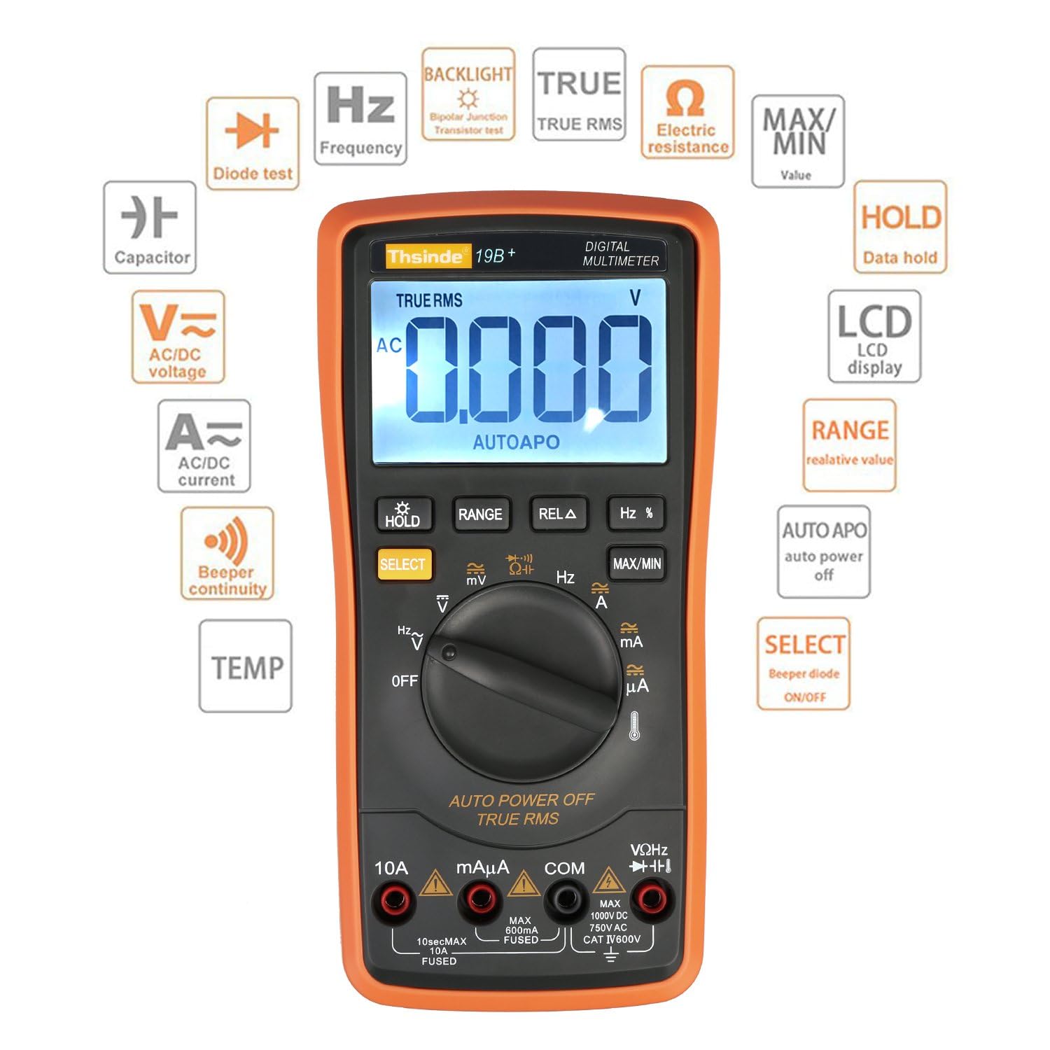
This image illustrates the various functions and symbols present on the Thsinde Digital Multimeter, including Diode test, Frequency, Backlight, True RMS, Electric resistance, Max/Min value, Capacitor, AC/DC voltage, AC/DC current, Data hold, LCD display, Relative value, Auto power off, Beeper continuity, Temperature, and Select button.
3.2 Internal Components
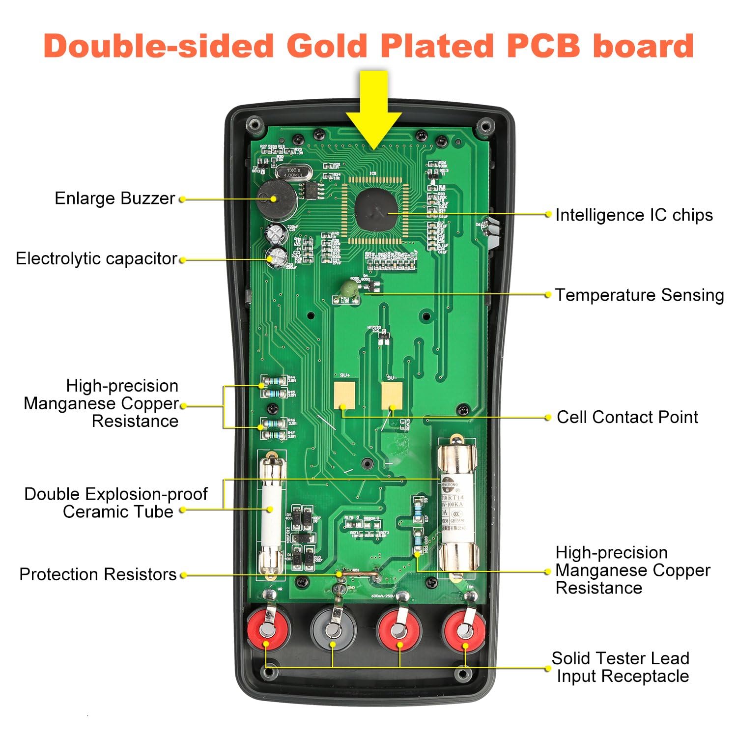
This image displays the internal components of the multimeter, highlighting the double-sided gold-plated PCB board, intelligence IC chips, electrolytic capacitor, temperature sensing, high-precision manganese copper resistance, double explosion-proof ceramic tube, protection resistors, cell contact point, and solid tester lead input receptacles.
4. Setup
4.1 Battery Installation
The multimeter requires a 9V battery for operation. To install or replace the battery:
- Ensure the multimeter is turned OFF and test leads are disconnected.
- Locate the battery compartment cover on the back of the unit.
- Use a screwdriver to remove the screw securing the cover.
- Carefully remove the cover.
- Connect a new 9V battery to the battery clips, observing correct polarity.
- Place the battery into the compartment and replace the cover, securing it with the screw.
4.2 Connecting Test Leads
Always connect the black test lead to the COM jack. Connect the red test lead to the appropriate input jack based on the measurement you intend to make:
- For Voltage, Resistance, Frequency, Capacitance, Diode, and Continuity: Connect the red lead to the VΩHz jack.
- For Current (up to 600mA): Connect the red lead to the mAμA jack.
- For High Current (up to 10A): Connect the red lead to the 10A jack.
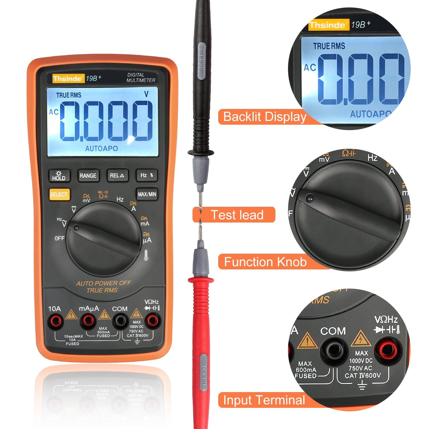
This image provides a closer look at the multimeter, its backlit display, the function knob for selecting measurement modes, and the input terminals for connecting test leads.
5. Operating Modes
Turn the function switch to the desired measurement mode. Use the SELECT button to toggle between AC/DC or other sub-functions if applicable.
5.1 Voltage Measurement (AC/DC)
- Set the function switch to V~ (AC Voltage) or V- (DC Voltage).
- Connect the black test lead to the COM jack and the red test lead to the VΩHz jack.
- Connect the test probes in parallel across the component or circuit to be measured.
- Read the voltage value on the LCD display.
5.2 Current Measurement (AC/DC)
- Set the function switch to A~ (AC Current) or A- (DC Current).
- Connect the black test lead to the COM jack. For currents up to 600mA, connect the red lead to the mAμA jack. For currents up to 10A, connect the red lead to the 10A jack.
- Important: Disconnect power to the circuit. Open the circuit where current is to be measured and connect the multimeter in series with the load.
- Apply power to the circuit and read the current value.
5.3 Resistance Measurement
- Set the function switch to Ω.
- Connect the black test lead to the COM jack and the red test lead to the VΩHz jack.
- Important: Ensure the circuit is de-energized and all capacitors are discharged before measuring resistance.
- Connect the test probes across the component to be measured.
- Read the resistance value on the LCD display.
5.4 Continuity Test
- Set the function switch to the continuity symbol (speaker icon).
- Connect the black test lead to the COM jack and the red test lead to the VΩHz jack.
- Connect the test probes across the circuit or component.
- If the resistance is below approximately 50Ω, the buzzer will sound, indicating continuity.
5.5 Capacitance Measurement
- Set the function switch to the capacitance symbol (capacitor icon).
- Connect the black test lead to the COM jack and the red test lead to the VΩHz jack.
- Important: Ensure the capacitor is fully discharged before measurement to prevent damage to the multimeter.
- Connect the test probes across the capacitor terminals.
- Read the capacitance value on the LCD display.
5.6 Frequency Measurement
- Set the function switch to Hz.
- Connect the black test lead to the COM jack and the red test lead to the VΩHz jack.
- Connect the test probes across the signal source.
- Read the frequency value on the LCD display.
5.7 Diode Test
- Set the function switch to the diode symbol.
- Connect the black test lead to the COM jack and the red test lead to the VΩHz jack.
- Connect the red probe to the anode and the black probe to the cathode of the diode.
- The display will show the forward voltage drop. Reverse the probes; the display should show OL (Open Loop) for a good diode.
5.8 Transistor Test (hFE)
This multimeter supports transistor hFE testing. Refer to the specific markings on the multimeter for NPN/PNP transistor insertion points and follow the on-screen instructions or manual for detailed steps.
5.9 Temperature Measurement
- Set the function switch to TEMP.
- Connect the temperature probe to the VΩHz and COM jacks, observing polarity.
- Place the tip of the temperature probe on the object or area whose temperature is to be measured.
- Read the temperature value on the LCD display. The unit can display in Celsius or Fahrenheit.

This image shows the multimeter performing a temperature test, displaying '0022' degrees Celsius. It indicates the temperature measurement range from -20°C to 1000°C (0°F to 1832°F).
6. Maintenance
6.1 Battery Replacement
Refer to Section 4.1 for detailed instructions on battery replacement. Always use a fresh 9V battery when the low battery indicator appears on the display.
6.2 Fuse Replacement
If the current measurement function stops working, the fuse may need replacement. The multimeter uses double explosion-proof ceramic tube fuses.
- Ensure the multimeter is turned OFF and test leads are disconnected.
- Open the back cover as described for battery replacement.
- Carefully locate and remove the blown fuse(s). There are typically two fuses: one for mA/μA range (e.g., 600mA) and one for the 10A range (e.g., 10A).
- Replace with fuses of the exact same type and rating. Using incorrect fuses can damage the multimeter or pose a safety hazard.
- Securely replace the back cover.
6.3 Cleaning
Wipe the case with a damp cloth and mild detergent. Do not use abrasives or solvents. Keep the input terminals free from dirt and moisture.
7. Troubleshooting
- No Display or Faint Display: Check battery installation and replace if necessary.
- Incorrect Readings:
- Ensure test leads are correctly connected to the appropriate input jacks.
- Verify the function switch is set to the correct measurement mode.
- Check for proper contact between probes and the circuit.
- Ensure the battery is not low.
- Current Measurement Not Working: Check and replace the fuse(s) as described in Section 6.2.
- "OL" (Overload) Display: The measured value exceeds the selected range. Switch to a higher range (if in manual ranging) or ensure the input is within the multimeter's maximum limits.
8. Specifications
| Feature | Specification |
|---|---|
| Model Number | TH053 |
| Display | 6000 Counts, Backlit LCD |
| True RMS | Yes |
| Ranging | Auto and Manual |
| DC Voltage Range | Up to 1000V |
| AC Voltage Range | Up to 750V |
| DC Current Range | Up to 10A |
| AC Current Range | Up to 10A |
| Resistance Range | Up to 60MΩ |
| Capacitance Range | Up to 60mF |
| Frequency Range | Up to 10MHz |
| Temperature Range | -20°C to 1000°C (0°F to 1832°F) |
| Diode Test | Yes |
| Continuity Test | Yes (with buzzer) |
| Transistor Test (hFE) | Yes |
| Power Source | 9V Battery |
| Auto Power Off | Yes |
| Item Weight | 320 g |
| Package Dimensions | 22.3 x 16.2 x 6.2 cm |
| Manufacturer | Thsinde |
| UPC | 699747921176 |

This image provides the physical dimensions of the Thsinde Digital Multimeter, including its overall size (18.5cm/7.28inch height, 9cm/3.54inch width, 4.5cm/1.77inch thickness) and the LCD screen dimensions (6.5cm/2.56inch width, 4cm/1.57inch height).
9. Warranty and Support
For warranty information, technical support, or service inquiries, please contact Thsinde customer service directly. Keep your purchase receipt as proof of purchase.

This image shows the Thsinde Digital Multimeter along with its accessories, such as test leads and a temperature probe, neatly organized within a protective carrying case.