Introduction
This manual provides detailed instructions for the installation, operation, and maintenance of the BV-Tech POE-SW802-DIN 8-Port PoE+ Industrial DIN Rail Switch. This device is designed for efficient power and data distribution in various networking environments, supporting IP cameras, VoIP phones, and wireless access points.
Product Overview
The BV-Tech POE-SW802-DIN is an unmanaged 8-port PoE+ switch with additional Gigabit Ethernet and SFP uplink ports, housed in a durable metal casing suitable for industrial applications. It supports IEEE802.3af/at standards, providing up to 30 watts per PoE port.

Image 1: Front view of the BV-Tech POE-SW802-DIN switch. This image displays the compact black metal housing of the switch, highlighting its 8 PoE+ ports, 1 Gigabit Ethernet uplink port, and 1 SFP uplink port.

Image 2: Dimensions of the BV-Tech POE-SW802-DIN switch. This image provides a visual representation of the switch's physical size, indicating its length, width, and height for installation planning.
Key Features:
- 8 PoE+ Ports: Provides power and data over Ethernet to compatible devices (10/100Mbps, IEEE802.3af/at, up to 30W per port).
- 1 Gigabit Ethernet Uplink: High-speed data transfer (10/100/1000Mbps).
- 1 SFP Uplink: Supports fiber optic connections for extended network reach (1000Mbps Base-X).
- Industrial Grade Design: Durable metal casing for reliability in diverse environments, including wide temperature ranges.
- DIN Rail Mount: Easy and secure installation on standard DIN rails.
- Unmanaged Switch: Plug-and-play operation with no complex configuration required.
What's in the Box
Upon opening the product packaging, verify that all the following items are included:
- BV-Tech POE-SW802-DIN 8-Port PoE+ Industrial DIN Rail Switch
- Power Adapter (96W)
- Power Cord
- DIN Rail Adapter (pre-attached or included for installation)
- Screws for DIN Rail Adapter (if not pre-attached)

Image 3: Contents of the product box. This image shows the BV-Tech POE-SW802-DIN switch, its power adapter, and power cord, neatly arranged in their packaging.
Setup and Installation
1. Power Connection
- Connect the power cord to the power adapter.
- Plug the power adapter into the DC48-57V input port on the switch.
- Plug the power cord into a suitable electrical outlet.
- The PWR LED indicator on the switch will illuminate, indicating successful power-up.

Image 4: Power adapter for the BV-Tech POE-SW802-DIN. This image shows the external power adapter and its connection to the switch's power input, highlighting the DC48-57V input.
Note: The switch also features a secondary power input (PWR1 & PWR2 DC48-57V) via a Phoenix connector for redundant power supply or specific industrial setups. Ensure correct polarity if using this input.
2. Network Connections

Image 5: Port layout of the BV-Tech POE-SW802-DIN switch. This image clearly labels the 8 PoE+ ports (10/100 Base-T), the 1 Gigabit Ethernet uplink port (10/100/1000 Base-T), and the 1 SFP uplink port (1000 Base-X).
- PoE+ Device Connection: Connect your PoE-compatible devices (e.g., IP cameras, VoIP phones, wireless access points) to ports 1-8 using standard Ethernet cables. These ports will automatically detect and provide power to compliant devices.
- Gigabit Ethernet Uplink: Connect your network router or main switch to the Gigabit Ethernet uplink port (Port 9, 10/100/1000 Base-T) for high-speed data transfer.
- SFP Uplink: For fiber optic network connections, insert a compatible SFP module into the SFP uplink port (Port 10, 1000 Base-X) and connect your fiber cable.
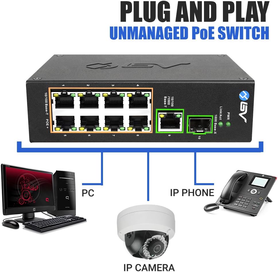
Image 6: Plug and Play connection diagram. This image illustrates how various devices like PCs, IP phones, and IP cameras connect to the switch, demonstrating its unmanaged, plug-and-play functionality.
3. DIN Rail Mounting
The POE-SW802-DIN switch is equipped with a DIN rail adapter for easy installation in industrial cabinets or on walls.
- Ensure the DIN rail adapter is securely attached to the back of the switch using the provided screws.
- Align the top edge of the DIN rail adapter with the top lip of the DIN rail.
- Push the bottom of the switch towards the DIN rail until it clicks into place, securing the switch.
- To remove, pull the bottom of the switch away from the rail and lift upwards.

Image 7: Close-up of the DIN rail adapter on the back of the switch. This image shows the mechanism for attaching the switch to a DIN rail, emphasizing its industrial mounting capability.
Installation Demonstration Video:
Video 1: Unboxing and DIN Rail Installation Guide. This video demonstrates the unboxing of the BV-Tech POE-SW802-DIN switch and provides a visual guide on how to easily install it onto a DIN rail, showcasing the simplicity and efficiency of the mounting process.
Operating Instructions
The BV-Tech POE-SW802-DIN is an unmanaged switch, meaning it operates on a plug-and-play basis without requiring complex software configuration. Once powered on and connected, it automatically detects and provides network connectivity and power to connected devices.
LED Indicators:
- PWR (Power): Illuminates green when the switch is receiving power.
- Link/Act (Link/Activity):
- Solid green: Indicates a stable network link.
- Flashing green: Indicates data activity on the port.
Maintenance
- Cleaning: Use a soft, dry cloth to clean the exterior of the switch. Do not use liquid or aerosol cleaners.
- Environment: Ensure the switch is operated within its specified temperature range (-40°C to 65°C) and humidity levels. Avoid exposing the device to excessive moisture or extreme temperatures.
- Firmware: As an unmanaged switch, firmware updates are generally not required.
Troubleshooting
- No Power (PWR LED off):
- Check if the power cord is securely connected to the switch and the electrical outlet.
- Verify the power adapter is functioning correctly.
- Ensure the electrical outlet is active.
- No Link/Activity (Link/Act LED off):
- Ensure the Ethernet cable is securely connected to both the switch port and the connected device.
- Verify the connected device is powered on and functioning correctly.
- Try a different Ethernet cable or switch port to rule out cable or port issues.
- PoE Device Not Receiving Power:
- Confirm the connected device is PoE-compatible (IEEE802.3af/at).
- Check the power requirements of the device to ensure it does not exceed the 30W per port limit or the total power budget of the switch.
- Ensure the Ethernet cable is of good quality and supports PoE.
Specifications
| Feature | Detail |
|---|---|
| Brand | BV-Tech |
| Model Number | POE-SW802-DIN |
| Number of Ports | 10 (8 PoE+, 1 Gigabit Ethernet, 1 SFP) |
| PoE Standard | IEEE802.3af/at |
| Maximum Power per PoE Port | 30 Watts |
| Data Transfer Rate | 10/100Mbps (PoE ports), 10/100/1000Mbps (Gigabit Uplink), 1000Mbps (SFP Uplink) |
| Switch Type | Unmanaged PoE |
| Voltage Input | 48-57 Volts DC |
| Operating Temperature | -40°C to 65°C (-40°F to 149°F) |
| Case Material | Metal |
| Item Dimensions (L x W x H) | 9"L x 3.94"W x 1.65"H |
| Item Weight | 1.19 Pounds |
| UPC | 813076028577 |
Warranty Information
The BV-Tech POE-SW802-DIN switch comes with a 1-year manufacturer's warranty. This warranty covers defects in materials and workmanship under normal use. For warranty claims or detailed terms and conditions, please contact BV-Tech customer support.
Support
For technical assistance, product inquiries, or support, please visit the official BV-Tech website or contact their customer service department. Refer to the product packaging or the BV-Tech website for the most current contact information.
BV-Tech Store: Visit the BV Store on Amazon