
UEETEK MT87
UEETEK MT87 Digital Clamp Multimeter Instruction Manual
Model: MT87
1. Introduction
The UEETEK MT87 Digital Clamp Multimeter is a compact, battery-powered device designed for electrical measurements. It features a clamp jaw for non-contact AC current measurement and test leads for measuring DC voltage, resistance, and continuity. This manual provides detailed instructions for safe and effective operation, maintenance, and troubleshooting of your MT87 multimeter.
Key Features:
- Digital display for clear readings.
- Clamp jaw for AC current measurement up to 400A.
- Measures DC voltage up to 600V.
- Resistance measurement.
- Continuity buzzer.
- Data Hold function.
2. Safety Information
Always observe the following safety precautions when using the MT87 Digital Clamp Multimeter to prevent electric shock, injury, or damage to the meter or equipment under test.
- Do not apply voltage to the clamp meter when the function switch is set to current measurement.
- Do not exceed the maximum input values for any function.
- Ensure the test leads are properly connected and the function switch is set to the correct range before making measurements.
- Exercise extreme caution when working with live circuits.
- Do not use the meter if it appears damaged or if the test leads are frayed.
- Remove the test leads from the circuit before changing functions.
- Replace batteries when the low battery indicator appears to ensure accurate readings.
3. Product Components and Overview
Familiarize yourself with the different parts of the MT87 Digital Clamp Multimeter.
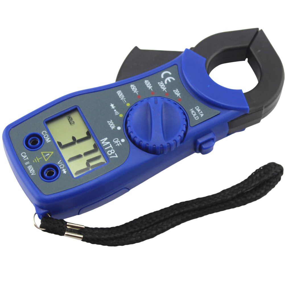
Figure 3.1: Front view of the MT87 Digital Clamp Multimeter. This image displays the main components including the digital display, the rotary function switch, the clamp jaw for current measurement, and the input terminals for test leads. A black wrist strap is attached to the bottom right.
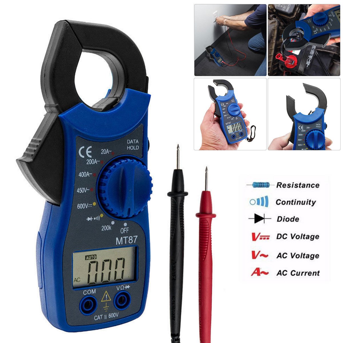
Figure 3.2: MT87 Clamp Multimeter with included test leads. This image shows the multimeter alongside its red and black test probes. On the right, a legend explains the symbols for Resistance, Continuity, Diode, DC Voltage, AC Voltage, and AC Current, indicating the meter's capabilities.
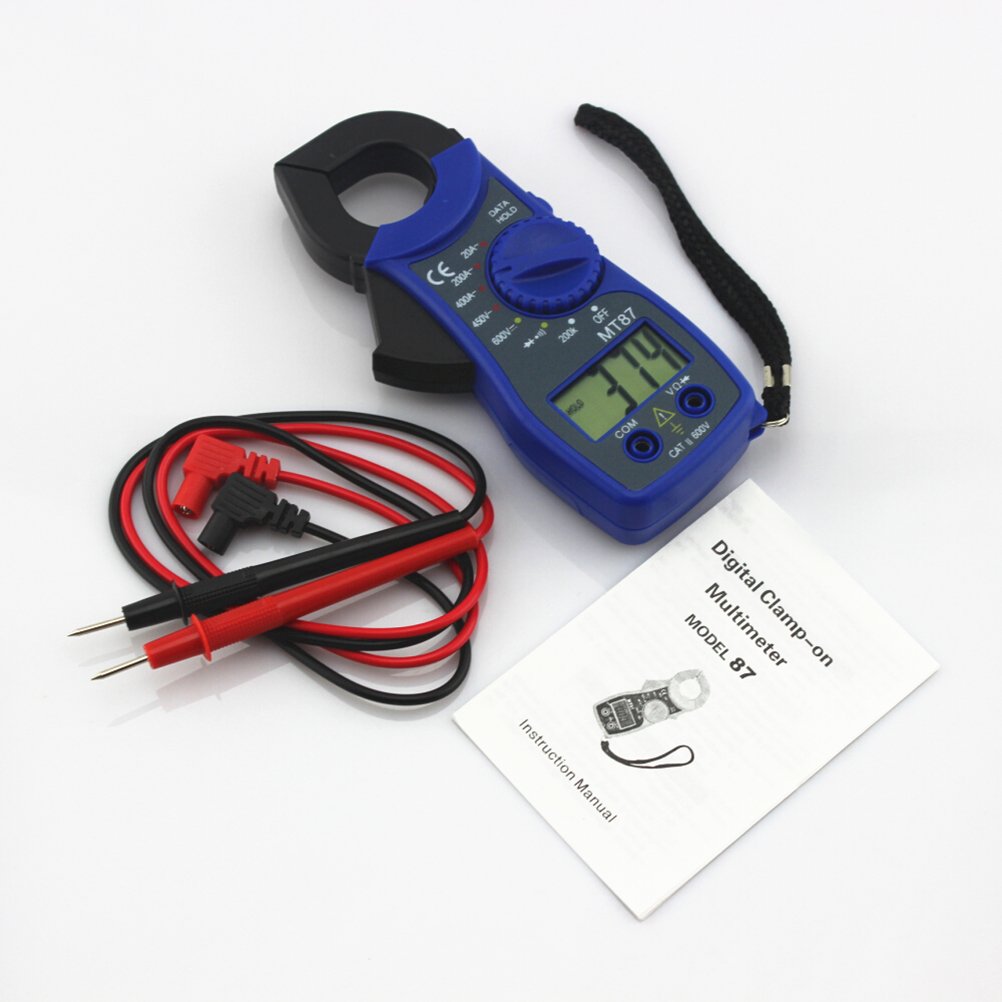
Figure 3.3: Contents of the MT87 Clamp Multimeter package. This image displays the multimeter, a pair of red and black test leads, and the instruction manual titled "Digital Clamp-on Multimeter Model 87 Instruction Manual", all laid out on a white surface.
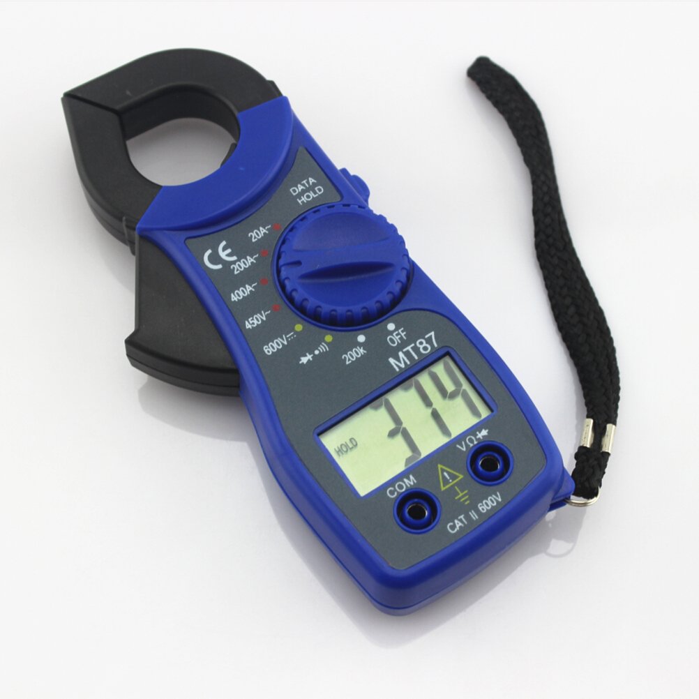
Figure 3.4: Angled view of the MT87 Clamp Multimeter. This image provides a closer look at the device, highlighting the digital display which shows a reading of "3.74", the "HOLD" button, and the input jacks. The blue casing and black clamp are clearly visible.

Figure 3.5: Rear view of the MT87 Clamp Multimeter. This image shows the back of the device, including the battery compartment cover, a "Q.C. PASSED" sticker, and printed specifications such as "IEC1010-1 CAT.II 600V" and "SIZE AAA 1.5V x 2", indicating it uses two AAA batteries.
Main Parts:
- Clamp Jaw: Used for non-contact measurement of AC current.
- Function Switch: Rotary dial to select measurement functions (AC Current, DC Voltage, Resistance, Continuity, Diode).
- LCD Display: Shows measurement readings, units, and indicators.
- "HOLD" Button: Freezes the current reading on the display.
- Input Jacks: "COM" (common/negative) and "VΩ+" (positive) for connecting test leads for voltage, resistance, continuity, and diode measurements.
- Battery Compartment: Located on the back, holds two AAA batteries.
4. Setup and Initial Operation
4.1. Battery Installation
The MT87 Multimeter requires two AAA 1.5V batteries for operation.
- Ensure the meter is turned OFF.
- Locate the battery compartment cover on the back of the meter (refer to Figure 3.5).
- Use a screwdriver to loosen the screw on the battery cover.
- Remove the cover and insert two AAA batteries, observing the correct polarity (+/-) as indicated inside the compartment.
- Replace the battery cover and secure it with the screw.
4.2. Connecting Test Leads
For voltage, resistance, continuity, and diode measurements, connect the supplied test leads:
- Insert the black test lead into the "COM" (common) input jack.
- Insert the red test lead into the "VΩ+" input jack.
5. Operating Instructions
Before taking any measurement, ensure the meter is set to the correct function and range.
5.1. AC Current Measurement (Clamp)
This function uses the clamp jaw to measure AC current without breaking the circuit.
- Turn the function switch to the desired AC current range (e.g., 20A, 200A, 400A).
- Press the trigger to open the clamp jaw.
- Enclose only one conductor of the circuit within the clamp jaw. Do not clamp around multiple conductors, as this will result in an inaccurate reading (the magnetic fields will cancel out).
- Release the trigger to close the clamp jaw securely around the conductor.
- Read the AC current value on the LCD display.
5.2. DC Voltage Measurement
Measures direct current voltage.
- Connect the black test lead to "COM" and the red test lead to "VΩ+".
- Turn the function switch to the desired DC Voltage range (e.g., 600V).
- Connect the test leads in parallel to the circuit or component you wish to measure.
- Read the DC voltage value on the LCD display. Observe polarity if indicated.
5.3. Resistance Measurement
Measures electrical resistance in Ohms (Ω).
- Connect the black test lead to "COM" and the red test lead to "VΩ+".
- Turn the function switch to the Resistance range (e.g., 200kΩ).
- Ensure the circuit or component under test is de-energized before measuring resistance.
- Connect the test leads across the component.
- Read the resistance value on the LCD display.
5.4. Continuity Test
Checks for an open or closed circuit with an audible buzzer.
- Connect the black test lead to "COM" and the red test lead to "VΩ+".
- Turn the function switch to the Continuity (•))) position.
- Ensure the circuit or component under test is de-energized.
- Connect the test leads across the circuit or component.
- If the resistance is below a certain threshold (typically 50Ω), the buzzer will sound, indicating continuity.
5.5. Diode Test
Tests the forward voltage drop of a diode.
- Connect the black test lead to "COM" and the red test lead to "VΩ+".
- Turn the function switch to the Diode (▲) position.
- Ensure the diode is de-energized and isolated from the circuit.
- Connect the red test lead to the anode and the black test lead to the cathode of the diode.
- The display will show the forward voltage drop (typically 0.5V to 0.8V for silicon diodes). Reversing the leads should show an "OL" (Open Loop) reading for a good diode.
5.6. Data Hold Function
Press the "HOLD" button to freeze the current reading on the display. Press it again to release the hold and resume live readings.
6. Maintenance
6.1. Cleaning
To clean the meter, wipe the case with a damp cloth and mild detergent. Do not use abrasives or solvents. Ensure the meter is completely dry before use.
6.2. Battery Replacement
When the low battery indicator appears on the display, replace the batteries promptly to ensure accurate measurements. Refer to Section 4.1 for battery installation instructions.
6.3. Fuse Replacement
The MT87 Digital Clamp Multimeter typically does not have user-replaceable fuses for current ranges measured by the clamp. For voltage and resistance measurements, if the meter malfunctions, consult a qualified technician. Do not attempt to open the meter casing beyond the battery compartment unless specifically instructed by the manufacturer.
7. Troubleshooting
| Problem | Possible Cause | Solution |
|---|---|---|
| No display or dim display | Dead or low batteries | Replace batteries (refer to Section 4.1). |
| "OL" (Overload) displayed | Input value exceeds selected range or meter's maximum capacity. Open circuit in continuity/resistance test. | Select a higher range. Ensure circuit is closed for continuity/resistance. |
| Inaccurate readings | Low battery. Incorrect function/range selected. External interference. | Replace batteries. Verify function switch setting. Move away from strong electromagnetic fields. |
| No current reading with clamp | Clamping around multiple conductors. DC current being measured. | Ensure only one conductor is within the clamp. Note: This meter measures AC current only. |
8. Specifications
| Parameter | Value |
|---|---|
| Model | MT87 |
| Brand | UEETEK |
| AC Current Range | 20A, 200A, 400A |
| DC Voltage Range | 600V |
| Resistance Range | 200kΩ |
| Continuity Test | Yes (with buzzer) |
| Diode Test | Yes |
| Data Hold | Yes |
| Power Source | 2 x AAA 1.5V Batteries |
| Dimensions (L x W x H) | 5.91 x 2.76 x 1.18 inches (15 x 7 x 3 cm) |
| Weight | 5.12 ounces (145 grams) |
| Safety Rating | CAT II 600V |
9. Warranty and Support
For warranty information and technical support, please refer to the documentation provided with your purchase or contact UEETEK customer service through their official website or the retailer where the product was purchased. Please have your product model number (MT87) and purchase date available when contacting support.
Related Documents - MT87
 |
Digital Clamp-on Multimeter MT87: Instruction Manual and Specifications Comprehensive instruction manual and technical specifications for the MT87 Digital Clamp-on Multimeter, covering safety, operation, and detailed performance characteristics. |
 |
UEETEK DC 12V Brushless Submersible Water Pump Product Manual Comprehensive product manual for the UEETEK DC 12V Brushless Submersible Water Pump, covering installation, safety, maintenance, and usage scenarios. |
 |
ANENG MT87 Digital Clamp-on Multimeter: User Manual & Specifications Explore the ANENG MT87 Digital Clamp-on Multimeter. This comprehensive manual covers safety, features, specifications, and operation for accurate electrical measurements. |
 |
Everwell MT87 Digital Clamp Meter: Operator's Instruction Manual Comprehensive operator's instruction manual for the Everwell MT87 Digital Clamp Meter. Includes specifications, operation guidelines, safety precautions, and warranty information. |
 |
ANENG MT87 Digital Clamp Meter User Manual Comprehensive user manual for the ANENG MT87 Digital Clamp Meter, covering technical specifications, measurement methods, and maintenance instructions for electrical testing. |
Ask a question about this manual
Ask about setup, troubleshooting, compatibility, parts, safety, or missing instructions. Manuals+ will review the question and use this page’s manual context to help answer it.