1. Introduction
This manual provides detailed instructions for the installation, operation, and maintenance of your SolarEpic Tracer4215BN MPPT Solar Charge Controller. This advanced controller is designed to efficiently manage power from your solar panels to charge various battery types, including Lithium and Lead-Acid, ensuring optimal performance and longevity of your solar power system. Please read this manual thoroughly before installation and use to ensure safe and correct operation.
2. Product Overview
The Tracer4215BN MPPT Solar Charge Controller is a robust device featuring a negative grounding design and an advanced Maximum Power Point Tracking (MPPT) algorithm for high efficiency. It supports a wide range of battery types and offers a battery-less mode for direct load powering.
2.1 Main Components

Figure 2.1: EPEVER MPPT Solar Charge Controller (left) with MT52 Remote Meter, temperature sensor, and PC communication cable (right).
The package includes the main charge controller unit, an MT52 remote meter for monitoring and configuration, a battery temperature sensor, and a PC communication cable (USB to RS485 converter) for software monitoring.
2.2 Connection Ports
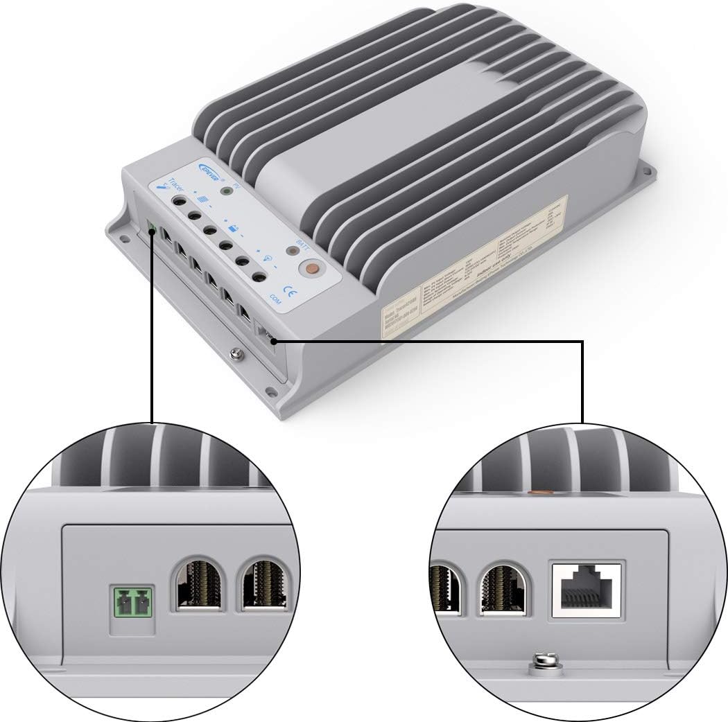
Figure 2.2: Detailed view of the controller's connection terminals for PV input, battery, load, and communication.
The controller features clearly labeled terminals for PV input, battery connection, and DC load output. A dedicated RJ45 port is available for connecting the MT52 remote meter and the PC communication cable.
3. Setup and Installation
Proper installation is crucial for the safe and efficient operation of your solar charge controller. Ensure all connections are secure and follow the wiring diagram carefully.
3.1 Wiring Diagram

Figure 3.1: Example wiring diagram for a solar power system including the SolarEpic 4215BN Charge Controller, solar panels, battery bank, inverter, and load.
Connect the components in the following order: Battery > Load > PV Array. Always disconnect in the reverse order. Ensure proper polarity for all connections. The controller supports series wiring of solar panels up to 150V Max PV input.
3.2 MT52 Remote Meter Installation

Figure 3.2: The MT52 remote meter and its mounting frame, designed for easy integration into your system panel.
The MT52 remote meter provides real-time monitoring and allows for parameter adjustments. Connect it to the controller via the provided RJ45 cable. The meter can be surface-mounted using its frame.
3.3 Temperature Sensor and PC Communication

Figure 3.3: The battery temperature sensor, essential for accurate temperature compensation during charging.
Connect the temperature sensor to the designated port on the controller to enable temperature compensation for charging parameters, prolonging battery life. For PC monitoring, use the USB to RS485 converter cable.

Figure 3.4: The USB to RS485 converter cable, used for connecting the controller to a PC for advanced monitoring and configuration via Solar Station PC software.
4. Operating Instructions
The Tracer4215BN controller is designed for user-friendly operation with intelligent charging algorithms.
4.1 Battery Type Selection
The controller supports various battery types: Lithium (LiFePO4 (4S/8S), Li(NiCoMn)O2 (3S/6S/7S)), and all Lead-Acid batteries (Sealed, Gel, Flooded). Ensure the correct battery type is selected in the MT52 remote meter settings or via PC software for optimal charging and battery health.
4.2 Battery-less Mode
A new feature allows the controller to power DC loads directly from the solar panel without a connected battery. This mode is ideal for applications where continuous battery storage is not required.
4.3 Communication Interface
The RS-485 communication bus interface and standard MODBUS interface are available for advanced monitoring and control. This allows integration with external systems or PC software for detailed data logging and parameter adjustments.
5. Maintenance
Regular maintenance ensures the longevity and optimal performance of your solar charge controller.
- Visual Inspection: Periodically check all wiring connections for tightness and signs of corrosion. Ensure the controller's heat sink is free from dust and debris to allow for proper heat dissipation.
- Cleaning: Keep the controller and its display clean. Use a soft, dry cloth for cleaning. Avoid using abrasive cleaners or solvents.
- Environmental Check: Ensure the installation environment remains within the specified operating temperature range (-20°C to +70°C / -4°F to 158°F) and is free from excessive moisture or direct sunlight.
- Firmware Updates: Check the manufacturer's website for any available firmware updates to ensure your controller has the latest features and bug fixes.
6. Troubleshooting
This section addresses common issues you might encounter with your solar charge controller.
| Problem | Possible Cause | Solution |
|---|---|---|
| MT52 Remote Meter not responding or incorrect password. | Incorrect password entry or temporary glitch. | The default password is "000000". Ensure you press the arrow button on all 6 digits to successfully enter the control parameter setup. Restarting the controller by disconnecting and reconnecting the battery may resolve temporary issues. |
| No charging from PV array. | PV array not connected, reversed polarity, or insufficient sunlight. | Check PV connections and polarity. Ensure adequate sunlight. Verify PV open circuit voltage is within the controller's limits (Max 150V). |
| Battery not charging or low charge. | Incorrect battery type setting, loose battery connections, or battery fault. | Verify correct battery type setting on MT52. Check battery connections for tightness. Test battery health. |
| Controller displays a "Warning". | System anomaly (e.g., over-temperature, over-voltage, short circuit). | Check the MT52 display for specific warning codes or messages. Refer to the full user manual (PDF) for detailed explanations of warning codes and their solutions. Address the underlying issue (e.g., reduce load, check wiring). |
7. Specifications
| Feature | Detail |
|---|---|
| Nominal System Voltage | 12V, 24V Auto Recognition |
| Rated Charge Current | 40A |
| Rated Load Current | 20A |
| Max PV Open Circuit Voltage | 150V / 138V |
| Max PV Input Power (12V Battery) | 520W |
| Max PV Input Power (24V Battery) | 1040W |
| Supported Battery Types | Lithium (LiFePO4, Li(NiCoMn)O2), Lead-Acid (Sealed, Gel, Flooded), USER mode |
| Grounding | Negative Grounding |
| Communication Interface | RS-485 (RJ45) |
| Operating Temperature | -20°C to +70°C (-4°F to 158°F) |
| Product Dimensions (L x W x H) | 11.93" x 7.2" x 2.52" |
| Item Weight | 7.7 pounds (3.5 Kilograms) |
| Model Number | Tracer4215BN-MT50 |
| UPC | 615068180009 |
8. Warranty and Support
SolarEpic offers a 2-year limited warranty for this product. For technical support, troubleshooting beyond this manual, or warranty claims, please contact SolarEpic customer service.
Additional resources: