1. Introduction
This manual provides essential information for the safe and efficient installation, operation, and maintenance of the RATTMMOTOR 2.2KW 220V Variable Frequency Drive (VFD). The VFD is designed to control the speed of 3-phase motors, commonly used with water-cooled or air-cooled spindle motors in applications such as CNC machines, textile equipment, and other industrial machinery.
Understanding the contents of this manual is crucial for maximizing the VFD's performance and ensuring user safety. Please read it thoroughly before attempting any installation or operation.

This image illustrates the wide range of applications for the RATTMMOTOR Variable Frequency Drive, including controlling fan water pumps, carving equipment, blender equipment, textile machinery, various electrical equipment, general industrial equipment, ball mills, and other specialized machinery.
2. Safety Information
WARNING: Improper installation or operation can lead to serious injury or death. Only qualified personnel should install, operate, and maintain this equipment.
- Electrical Shock Hazard: Ensure all power is disconnected before wiring or performing maintenance. Wait at least 10 minutes after power-off for capacitors to discharge. Verify zero voltage with a multimeter.
- Grounding: The VFD must be properly grounded according to local and national electrical codes.
- Overload Protection: Do not exceed the rated current or power of the VFD and connected motor.
- Environmental Conditions: Install the VFD in a clean, dry, well-ventilated area, free from corrosive gases, dust, and direct sunlight. Maintain the specified operating temperature range.
- Emergency Stop: Ensure an accessible emergency stop mechanism is in place for the entire system.
- Read Manual: Always refer to this instruction manual before installation, operation, or troubleshooting.
3. Product Overview
3.1 Key Features
- Control Model: SPWN
- Power: 2.2KW
- Input: 1 or 3 phase 220V, 0-50Hz/60Hz
- Output: 3 phase 220V, 0-400Hz
- Communication Control: RS-485
- Display: Five-digit display and status indicator lamps for frequency, current, revolution, voltage, counter, temperature, forward/reverse running, and fault status.
- General Control Functions: 4-segment reduction time (0.1-6500 seconds), V/F curve setting, adjustable torque (up to 10.0% start torque can reach 150%), Automatic Voltage Regulator (AVR), deceleration stop or free stop, DC brake, automatic reset, frequency tracking, PLC program control, transverse control, carrier adjustable up to 20kHz.
- Multi-Protection Functions: Overload protection, FUSE broken-motor stops protection, over-voltage/low-voltage protection, restart by frequency track after instantaneous stop, anti-stall during acceleration/deceleration, electronic circuit protection, over-heat protection, restriction of reverse running, direct start after power on, fault reset, parameter lock PID, one-drive-more.
3.2 Components and Design

This image displays the front panel of the VFD, highlighting the LED display, various control buttons (Run, Stop, Reverse/Forward, Shift, Program, Set, Increment, Decrement), and the speed control knob. Below the VFD, a table provides key specifications: Input Voltage (110V +/-15%), Output Voltage (110VAC), Input Frequency (48-63 Hz), Output Frequency (0-400 Hz), Output Phase (3 phase), Input Phase (1 phase), Output Current (20A), and Horsepower (3HP).

This image provides a closer look at the VFD's design elements. It highlights the DC cooling fan, emphasizing its low noise and high volume for effective heat dissipation. The 'Humanized Keyboard' refers to the control panel, noted for its reasonable layout, ease of operation, digital display, and clear interface. The 'Cutting-Edge Technology Motherboard' indicates the intelligent and efficient internal circuitry designed for strong protection performance.
4. Installation
4.1 Installation Environment
For optimal cooling and performance, the VFD must be installed vertically. Ensure adequate airflow around the unit. The operating temperature range is -10°C to 40°C. Avoid installation in areas with excessive dust, moisture, direct sunlight, or corrosive substances.
4.2 Wiring Diagrams
Proper wiring is critical for the safe and correct operation of the VFD. Refer to the diagrams below for connection details. Always ensure power is disconnected before making any connections.

This diagram illustrates the basic electrical connections for the VFD. It shows the input power terminals (R, S, T, E), connections for a potentiometer for speed control (10KΩ, VR+10V/5V, VI, ACM(GND)), various multi-input terminals (AI, FOR, REV, RST, SPM, SPH, SPL, DCM(COM)), RS485 communication ports, multi-output terminals (KA, FB, FA, FB, DRV, UPF, DCM), and the U.V.W output terminals for connecting to a three-phase motor. The diagram also notes that it serves as a reference, and the actual product should be taken as the standard, with the diagram subject to change without notice.

This detailed wiring diagram shows a practical setup. Input power is connected through circuit breakers to the R and S terminals of the VFD. The output power terminals U, V, and W are connected to the 3-phase motor. A ground connection is also shown. The image clearly depicts the VFD's control panel and the terminal block for connections.
4.3 Input/Output Terminals
- Multi-function Input Terminals (6): These can be configured for 8-speed control, program operation, 4-segment reduction switching, UP/DOWN functions, counter, and external emergency stop.
- Multi-function Output Terminals (5): These provide signals for running status, zero speed, counter, external abnormality, program operation, and other warnings.
5. Operation
5.1 Control Panel Functions
The VFD features a user-friendly control panel for easy operation and parameter setting. Refer to Figure 3.1 for a visual guide.
- RUN Button: Initiates motor operation.
- STOP/RESET Button: Stops motor operation or clears fault indications.
- FOR/REV Switch: Changes the direction of motor rotation (Forward/Reverse).
- SHIFT (DISP) Key: Used to shift between display modes or move the cursor during parameter editing.
- Increment Key (Up Arrow): Increases parameter values or navigates menus.
- Decrement Key (Down Arrow): Decreases parameter values or navigates menus.
- PRGM (Program) Key: Enters or exits the parameter setting mode.
- SET (Enter) Key: Confirms parameter settings or enters sub-menus.
- Speed Controller Knob: Adjusts the output frequency/motor speed.
5.2 Basic Operation
- Power On: Ensure all wiring is correct and secure. Apply power to the VFD. The LED display will illuminate.
- Set Frequency: Use the speed controller knob to set the desired output frequency. The display will show the current frequency.
- Start Motor: Press the RUN button. The motor will start accelerating to the set frequency.
- Change Direction: Use the FOR/REV switch to change the motor's rotation direction while running or before starting.
- Stop Motor: Press the STOP/RESET button. The motor will decelerate and stop.
5.3 Parameter Settings
The VFD offers extensive parameter settings for fine-tuning performance. Access these settings using the PRGM and SET keys, navigating with the arrow keys. Refer to the detailed parameter list in the full product manual for specific codes and functions. Key adjustable parameters include:
- V/F curve settings
- Acceleration/deceleration times
- Maximum/minimum output frequency
- Motor parameters (rated voltage, current, frequency)
- Control modes (e.g., vector control, V/F control)
6. Maintenance
Regular maintenance ensures the longevity and reliable operation of your VFD.
- Cleaning: Periodically clean the VFD's exterior, especially the cooling fan and heat sink fins, to prevent dust accumulation. Use a soft, dry cloth or compressed air. Ensure power is off before cleaning.
- Inspection: Regularly inspect all wiring connections for tightness and signs of wear or damage. Check for any unusual noises or vibrations during operation.
- Environmental Check: Ensure the operating environment remains within specified temperature and humidity limits.
- Fan Check: Verify that the cooling fan operates freely and without obstruction.
7. Troubleshooting
This section outlines common issues and potential solutions. For complex problems, contact technical support.
| Problem | Possible Cause | Solution |
|---|---|---|
| VFD does not power on | No input power; Blown fuse; Internal fault | Check power supply and circuit breakers; Replace fuse (if applicable, by qualified personnel); Contact support. |
| Motor does not run | Incorrect wiring; Parameter settings incorrect; Emergency stop active; Motor fault | Verify wiring against diagrams; Check VFD parameters (e.g., frequency, control mode); Release emergency stop; Inspect motor. |
| Over-current fault | Motor overload; Short circuit in motor/cables; Acceleration time too short | Reduce motor load; Check motor and cables for shorts; Increase acceleration time parameter. |
| Over-voltage fault | Input voltage too high; Deceleration time too short; Regenerative load | Check input voltage; Increase deceleration time parameter; Consider braking resistor for regenerative loads. |
| Under-voltage fault | Input voltage too low; Power supply instability | Check input voltage; Ensure stable power supply. |
| Over-heat fault | Insufficient cooling; Ambient temperature too high; Fan malfunction | Ensure proper ventilation and clear fan vents; Reduce ambient temperature; Check cooling fan operation. |
8. Specifications
Detailed technical specifications for the RATTMMOTOR 2.2KW 220V Variable Frequency Drive.
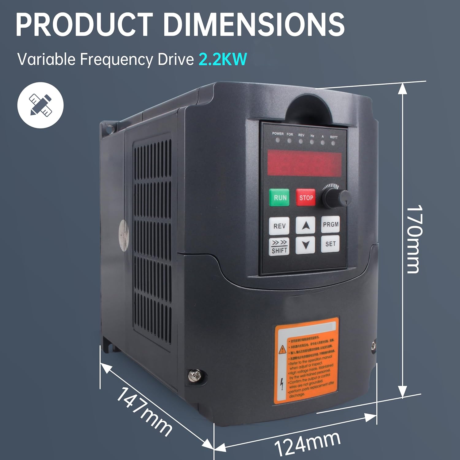
This image provides the physical dimensions of the VFD: Height is 170mm, Width is 147mm, and Depth is 124mm.
| Parameter | Value |
|---|---|
| Model Name | RATTMMOTOR Variable Frequency Drive |
| Part Number | HY02D223B |
| Power | 2.2 KW |
| Input Voltage | 220 Volts (1 or 3 phase) |
| Output Voltage | 220 Volts (3 phase) |
| Input Frequency | 0-50Hz/60Hz |
| Output Frequency | 0-400Hz |
| Control Model | SPWN |
| Communication | RS-485 |
| Operation Temperature | -10 ℃ to 40 ℃ |
| Vibration | Below 0.5G |
| Material | Plastic |
| Item Weight | 3.85 pounds |
| Product Dimensions | 0.01 x 5.91 x 4.92 inches (approx. 170 x 147 x 124 mm) |
9. Warranty and Support
RATTMMOTOR products are manufactured to high-quality standards. For specific warranty details, please refer to the documentation included with your purchase or contact the seller directly. In general, products are covered against manufacturing defects for a specified period from the date of purchase.
For technical assistance, troubleshooting guidance beyond this manual, or warranty claims, please contact RATTMMOTOR customer support. The seller is known for being responsive and knowledgeable about their products, providing excellent support.
You can often find contact information on the product packaging, the seller's storefront, or through the platform where the product was purchased.