1. Introduction
The eSynic ZT102 is a 6000-count auto-ranging digital multimeter designed for accurate electrical measurements. It utilizes a double-integral style A/D transform as its core, providing stable and reliable performance with overload protection and a clear LCD display. This device is suitable for use in laboratories, factories, and for general household electrical troubleshooting.
2. Safety Information
Always observe basic safety precautions when using this multimeter to prevent electric shock, injury, or damage to the meter or equipment under test. Read and understand all safety information before operation.
- Do not exceed the maximum input values for any function.
- Use caution when working with voltages above 30V AC RMS, 42V peak, or 60V DC. These voltages pose a shock hazard.
- Ensure the test leads are in good condition and properly seated in the input terminals.
- Do not operate the meter if it appears damaged or if the battery cover is not properly closed.
- Remove test leads from the circuit before changing functions.
- Replace batteries when the low battery indicator appears to ensure accurate readings.
- Always disconnect power to the circuit and discharge all high-voltage capacitors before testing resistance, continuity, diodes, or capacitance.
3. Package Contents
Verify that all items are present in the package:
- 1 x ZT102 Digital Multimeter
- 1 x Pair of Test Probes (Red and Black)
- 1 x Temperature Probe
- 1 x Storage Bag
- 2 x 1.5V AAA Batteries
- 1 x User Manual

4. Product Features
- 6000 Counts True RMS: Provides accurate readings for non-sinusoidal waveforms.
- Auto Ranging: Automatically selects the correct measurement range.
- Measurement Functions: AC/DC Voltage, AC/DC Current, Resistance, Capacitance, Diode, Continuity, Temperature, Frequency, and Duty Cycle.
- Overload Protection: Protection on all ranges, including restorable fuse protection and short-circuit protection.
- Backlit LCD Display: Large digits for clear visibility in various lighting conditions.
- Data Hold: Freezes the displayed reading for easy recording.
- Sample Rate: 3 times per second for quick measurements.
- Low Voltage Indication: Alerts when battery power is low.
- Auto Power Off: Conserves battery life by automatically shutting down after a period of inactivity.
- Compact Design: Product size of 130 x 65 x 30 mm and net weight of 190g for portability.
5. Product Diagram

- LED Screen: Displays measurement readings and indicators.
- HOLD/Backlit Button: Press to hold the current reading; long press to activate/deactivate backlight.
- SELECT Button: Toggles between different functions within a rotary switch position (e.g., AC/DC voltage, diode/continuity).
- Rotary Switch: Selects the primary measurement function.
- 10A Input Terminal: For measuring currents up to 10A.
- COM Input Terminal: Common (negative) terminal for all measurements.
- VΩHz-||-+ Input Terminal: For measuring voltage, resistance, frequency, capacitance, diode, and temperature.
6. Setup
6.1 Battery Installation
- Ensure the multimeter is turned OFF and all test leads are disconnected.
- Locate the battery compartment on the back of the meter.
- Use a screwdriver to open the battery compartment cover.
- Insert two 1.5V AAA batteries, observing the correct polarity (+ and -).
- Replace the battery compartment cover and secure it with the screw.

6.2 Connecting Test Probes
Always connect the black test lead to the COM terminal. Connect the red test lead to the appropriate input terminal based on the measurement function:
- For Voltage, Resistance, Capacitance, Diode, Continuity, Frequency, and Temperature measurements, connect the red lead to the VΩHz-||-+ terminal.
- For Current measurements (mA/A), connect the red lead to the 10A terminal for high current or the mA terminal for low current (if available, this model uses 10A for both).
7. Operating Instructions
7.1 General Operation
- Turn the rotary switch to the desired measurement function.
- If multiple functions are available at one switch position (e.g., AC/DC Voltage), press the SELECT button to toggle between them.
- Connect the test leads to the circuit or component under test.
- Read the measurement value on the LCD screen.
- To hold a reading, press the HOLD button. Press again to release.
- To activate the backlight, long press the HOLD button. Long press again to turn off.
- When finished, turn the rotary switch to the OFF position.
7.2 Specific Measurement Modes
7.2.1 Voltage Measurement (AC/DC)
- Set the rotary switch to ~V (AC Voltage) or V (DC Voltage). The meter will auto-range.
- Connect the red test lead to the VΩHz-||-+ terminal and the black lead to the COM terminal.
- Place the test probes across the component or circuit points where voltage is to be measured.

7.2.2 Resistance Measurement
- Set the rotary switch to Ω.
- Connect the red test lead to the VΩHz-||-+ terminal and the black lead to the COM terminal.
- Ensure the circuit is de-energized before measuring resistance.
- Place the test probes across the component to measure its resistance.

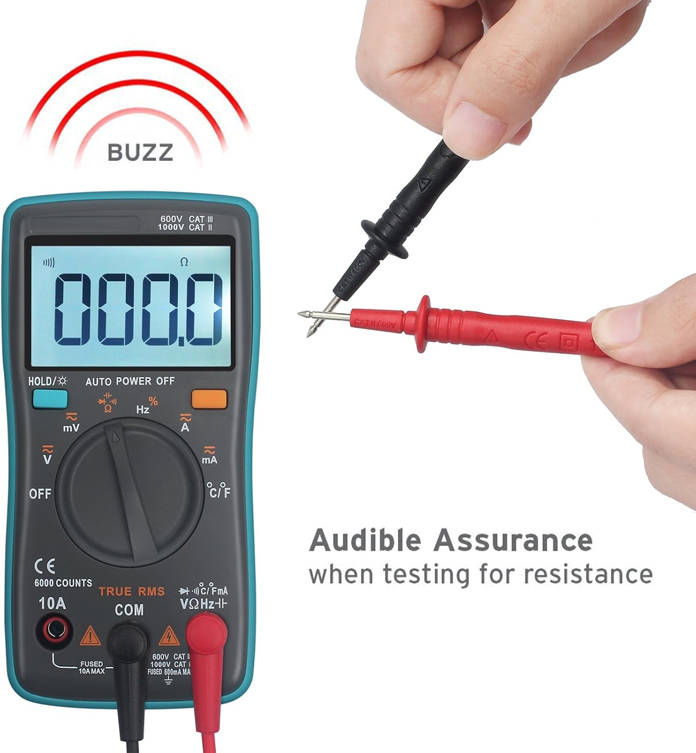
7.2.3 Continuity Test
- Set the rotary switch to Ω. Press SELECT until the continuity symbol ()))) appears.
- Connect the red test lead to the VΩHz-||-+ terminal and the black lead to the COM terminal.
- Ensure the circuit is de-energized.
- Place the test probes across the points to be tested. If continuity exists (resistance below approximately 50Ω), the buzzer will sound.
7.2.4 Current Measurement (AC/DC)
- Set the rotary switch to ~A (AC Current) or A (DC Current).
- Connect the red test lead to the 10A terminal and the black lead to the COM terminal.
- Important: To measure current, the meter must be connected in series with the circuit. Disconnect power to the circuit, open the circuit, and insert the meter in series.
- Apply power to the circuit and read the current.

7.2.5 Temperature Measurement
- Set the rotary switch to °C/°F.
- Connect the temperature probe to the VΩHz-||-+ and COM terminals, observing polarity.
- Place the tip of the temperature probe on or in the object whose temperature is to be measured.
- Read the temperature on the display. Press SELECT to switch between Celsius and Fahrenheit.

7.2.6 Capacitance, Diode, and Frequency/Duty Cycle
- For Capacitance, Diode, and Frequency/Duty Cycle, set the rotary switch to the corresponding position and use the SELECT button to cycle through the functions.
- Connect the red test lead to the VΩHz-||-+ terminal and the black lead to the COM terminal.
- For capacitance and diode tests, ensure the component is de-energized and discharged before testing.
8. Maintenance
8.1 Cleaning
Wipe the meter with a damp cloth and mild detergent. Do not use abrasives or solvents. Keep the terminals free from dirt and moisture.
8.2 Battery Replacement
When the low battery indicator appears on the display, replace the batteries as described in Section 6.1. Using the meter with low batteries may result in inaccurate readings.
8.3 Fuse Replacement
If the current measurement function stops working, the fuse may need replacement. Refer to the safety warnings on the back of the meter for fuse specifications. Only replace with a fuse of the same type and rating.
WARNING: To avoid electrical shock, remove test leads before replacing battery or opening case.
9. Troubleshooting
| Problem | Possible Cause | Solution |
|---|---|---|
| No display or dim display | Dead or low batteries | Replace batteries (Section 6.1) |
| Incorrect readings | Low batteries, incorrect function selected, poor lead connection | Replace batteries, select correct function, ensure leads are properly connected |
| Current measurement not working | Blown fuse | Replace fuse (refer to Section 8.3) |
| "OL" (Overload) displayed | Input value exceeds selected range or meter's maximum capacity | Select a higher range (if not auto-ranging) or verify the circuit's value is within meter limits. |
10. Specifications
| Measurement | Range | Accuracy |
|---|---|---|
| DC Voltage | 60mV/6V/60V/600V/1000V | ±(0.5%+3) |
| AC Voltage | 60mV/6V/60V/600V/750V | ±(1%+3) |
| DC/AC Current | 60mA/600mA/6A/10A | ±(1.5%+3) |
| Resistance | 600Ω/6KΩ/60KΩ/600KΩ/6MΩ/60MΩ | ±(0.5%+3) for most, ±(1.5%+3) for 60MΩ |
| Capacitance | 10nF/100nF/1uF/10uF/100uF/1000uF/10000uF | ±(2.0%+5) for most, ±(5.0%+5) for 1000uF/10000uF |
| Temperature | -20℃ to 1000℃ / -4℉ to 1832℉ | ±(2.5%+5) |
| Frequency | 5/50/500/5k/50k/500k/5M/10M Hz | ±(0.1%+3) |
| Duty Cycle | 1% to 99% | ±(1%) |
General Specifications:
- Display: 6000 Counts
- Measurement Method: Double integral A/D converter
- Auto Range & True RMS: Yes
- Diode Test: Yes
- Out of Range Display: OL
- Low Battery Indication: Yes
- Auto Power Off: Yes
- Short-circuit Protection: Yes
- Working Environment: 0~40°C, relative humidity <80%
- Power Source: 2 x 1.5V AAA Batteries
- Product Size: 130 x 65 x 30 mm
- Product Net Weight: 190g
11. Warranty
All eSynic products come with an 18-month warranty from the date of purchase. This warranty covers manufacturing defects and material faults under normal use. It does not cover damage caused by misuse, unauthorized modification, accident, or neglect.
12. Support
For technical assistance, warranty claims, or further inquiries, please contact eSynic customer support through your purchase platform or the official eSynic website. Please have your model number (ZT102) and purchase details ready when contacting support.