1. Introduction
This manual provides detailed instructions for the installation, operation, programming, and maintenance of your SASWELL SAS6000UTK-7 Thermostat. This thermostat is designed for use with various heating and cooling systems, including single-stage, multi-stage, and heat pump systems (up to 3-stage heat, 2-stage cool, with auxiliary or emergency heat). Please read this manual thoroughly before installation and use to ensure proper function and safety.
2. Safety Information
- Always turn off power to the heating/cooling system at the main breaker or fuse box before installing or servicing the thermostat.
- Installation should be performed by a qualified technician if you are unfamiliar with electrical wiring.
- Ensure all wiring connections are secure and comply with local electrical codes.
- Do not short-circuit the thermostat terminals.
- This thermostat is not compatible with millivolt systems.
3. Product Overview
The SASWELL SAS6000UTK-7 is a programmable thermostat featuring a large LCD digital display with backlight for easy readability. It offers flexible 7-day/4-period programming to optimize energy usage. The thermostat can be powered by two AA batteries or directly by the system via a C-wire (recommended for consistent backlight and operation).
Key Features:
- Compatibility with single-stage, multi-stage, and heat pump systems (up to 3-stage heat, 2-stage cool, with auxiliary or emergency heat).
- Optional 7-day programming with 4 periods per day (Wake, Leave, Return, Sleep).
- Large LCD digital display with adjustable backlight.
- Dual power options: 2 AA batteries or 24V AC C-wire connection.
- Vacation set-point override for energy savings.
- Accurate temperature control of +/-1°F (0.5°C).
- 12 or 24-hour clock display.
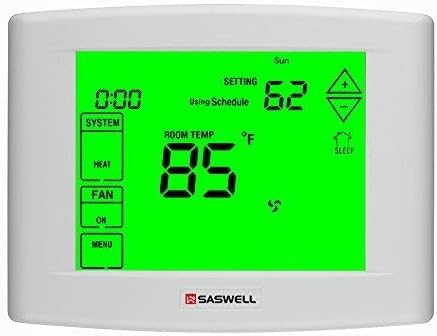
Figure 1: Front view of the SASWELL SAS6000UTK-7 Thermostat, showing the large green backlit LCD display with current temperature, setting, system mode, and fan status.
4. Installation
4.1 Tools Required:
- Screwdriver (Phillips and flathead)
- Drill (if new mounting holes are needed)
- Wire strippers (if wires are not pre-stripped)
- Level (optional, for aesthetic mounting)
4.2 Installation Steps:
- Turn Off Power: Locate the circuit breaker or fuse box that controls your heating and cooling system and turn off the power. Verify the power is off by attempting to operate your old thermostat.
- Remove Old Thermostat: Carefully remove the cover of your old thermostat. Take a picture of the wiring connections before disconnecting any wires. Label each wire with the corresponding terminal letter (e.g., R, C, Y, G, W, O/B).
- Mount Thermostat Base: Detach the front cover of the new SASWELL thermostat from its base. Position the new base on the wall, using existing holes if possible, or mark new holes. Drill pilot holes if necessary and secure the base to the wall using the provided screws.
- Connect Wires: Connect the labeled wires to the corresponding terminals on the new thermostat base. Refer to the wiring diagrams in Section 5 for specific configurations. Ensure the C-wire (common wire) is connected for optimal performance and backlight functionality.
- Install Batteries: Insert two fresh AA alkaline batteries into the battery compartment, observing polarity.
- Attach Thermostat to Base: Carefully align the thermostat body with the mounted base and snap it into place.
- Restore Power: Turn the power back on at the circuit breaker or fuse box.
5. Wiring Diagrams
The SASWELL SAS6000UTK-7 thermostat is compatible with various HVAC systems. Below are common wiring configurations. Always refer to your HVAC system's manual for specific wiring details. If you are unsure, consult a qualified HVAC technician.
Important Note for Heat Pump Systems: Some heat pump systems may require the O/B terminal to be wired differently than standard. If your air conditioning activates when heat is selected, or vice-versa, you may need to reverse the wiring on the O and B terminals. Consult your heat pump's manual or an HVAC professional for clarification.
Common Terminal Designations:
- R (Rh/Rc): 24V AC Power (Heating/Cooling)
- C: 24V AC Common (Required for continuous power and backlight)
- Y/Y1: Compressor Stage 1 (Cooling)
- Y2: Compressor Stage 2 (Cooling, for multi-stage systems)
- G: Fan Relay
- W/W1: Heat Stage 1 (Heating)
- W2: Heat Stage 2 (Heating, for multi-stage systems)
- O/B: Reversing Valve (Heat Pumps - O for Cool, B for Heat)
- Aux/E: Auxiliary/Emergency Heat (for heat pump systems)
Example Wiring (Heat Pump with Auxiliary Heat):
| Thermostat Terminal | Wire Function |
|---|---|
| R | 24V AC Power |
| C | 24V AC Common |
| Y1 | Compressor (Cooling) |
| G | Fan |
| O/B | Reversing Valve (typically O for cooling, B for heating) |
| Aux/E | Auxiliary/Emergency Heat |
Note: This table provides a general guide. Always match the wire labels from your old thermostat or your HVAC system's documentation to the new thermostat terminals.
6. Initial Setup and Configuration
After installation and restoring power, the thermostat will require initial configuration to match your specific HVAC system. Access the installer settings menu (refer to the on-screen prompts or a specific button combination, often holding a button for several seconds).
Common Settings to Adjust:
- System Type: Select between Conventional (Furnace/AC) or Heat Pump.
- Fan Type: Electric or Gas.
- O/B Valve: Set for cooling (O) or heating (B) activation in heat pump mode.
- Temperature Scale: Fahrenheit (°F) or Celsius (°C).
- Cycle Rate (Differential): Adjust the temperature swing before the system activates. The default "Fast Start" (0.5°C) may cause frequent cycling. Consider "Slow Start" (1.5°C) for less frequent operation and potentially longer equipment life. This can be set separately for heating and cooling.
- Backlight Settings: Choose between No Backlight, Touch Backlight (activates on touch), or Always On Backlight.
- Time and Date: Set the current time (12-hour or 24-hour format) and day of the week.
7. Operating Instructions
7.1 System Mode Selection:
Press the "SYSTEM" button to cycle through available modes:
- HEAT: The system will heat to your set temperature.
- COOL: The system will cool to your set temperature.
- OFF: The heating and cooling system is turned off. The fan can still be operated manually.
- AUTO: The thermostat automatically switches between heating and cooling to maintain the set temperature range.
- EMERGENCY HEAT (Heat Pump Systems): Activates auxiliary heat directly, bypassing the heat pump compressor. Use only when the heat pump is not functioning or during extreme cold.
7.2 Fan Mode Selection:
Press the "FAN" button to cycle through fan modes:
- AUTO: The fan runs only when the heating or cooling system is actively operating.
- ON: The fan runs continuously, regardless of heating or cooling calls.
7.3 Adjusting Temperature:
Use the Up (▲) and Down (▼) arrow buttons on the display to adjust the desired set temperature. The display will show the current room temperature and the set temperature.
7.4 Vacation Override:
This feature allows you to set a temporary energy-saving temperature while you are away. Consult the on-screen menu for specific steps to activate and deactivate vacation mode.
8. Programming (7-Day, 4-Period Schedule)
The SASWELL SAS6000UTK-7 allows for flexible 7-day programming with four distinct periods per day: Wake, Leave, Return, and Sleep. This enables you to customize temperature settings for different times of the day and days of the week to maximize comfort and energy efficiency.
Note: Some users have reported that the unit needs to be in the "OFF" system mode to access and program the schedule. If you encounter difficulties, try switching the system mode to OFF before entering the programming menu.
Programming Steps (General):
- Enter Program Mode: Press the "MENU" button, then navigate to the "PROGRAM" or "SCHEDULE" option.
- Select Day: Choose the day of the week you wish to program (e.g., Monday, All Weekdays, Weekend).
- Set Periods: For each period (Wake, Leave, Return, Sleep), set the desired start time and temperature for both heating and cooling.
- Repeat: Repeat for all desired days and periods.
- Save and Exit: Follow the on-screen prompts to save your settings and exit the programming mode.
Detailed instructions for navigating the programming menu are available on the thermostat's display. Familiarize yourself with the menu structure for optimal use.
9. Maintenance
9.1 Battery Replacement:
When the low battery indicator appears on the display, replace the two AA alkaline batteries promptly. Even with a C-wire connection, batteries serve as a backup to retain settings during power outages. To replace:
- Turn off power to the HVAC system at the breaker.
- Remove the thermostat from its wall plate.
- Remove the old batteries and insert new AA alkaline batteries, ensuring correct polarity.
- Reattach the thermostat to the wall plate and restore power.
9.2 Cleaning:
Clean the thermostat's exterior with a soft, damp cloth. Do not use abrasive cleaners or solvents. Avoid spraying liquids directly onto the thermostat.
10. Troubleshooting
| Problem | Possible Cause | Solution |
|---|---|---|
| Thermostat has no power/blank display. | Dead batteries, no C-wire power, tripped circuit breaker. | Replace batteries. Ensure C-wire is connected and receiving 24V AC. Check circuit breaker for HVAC system. |
| Heating/Cooling system not responding. | Incorrect wiring, system mode set to OFF, power off at breaker, system lockout. | Verify wiring connections (refer to Section 5). Ensure system mode is set to HEAT or COOL. Check circuit breaker. Wait 5 minutes for system lockout to reset. |
| Air conditioning runs when heat is selected (or vice-versa) on a heat pump. | O/B wire reversed or incorrect O/B setting in installer menu. | Consult your heat pump's manual to confirm if the reversing valve (O/B wire) should be energized for heating or cooling. Adjust wiring or the O/B setting in the thermostat's installer menu accordingly. |
| Thermostat cycles too frequently. | Cycle rate (differential) set too low. | Access installer settings (Section 6) and increase the cycle rate (e.g., change from "Fast Start" to "Slow Start"). |
| Difficulty programming schedule. | Thermostat not in correct mode for programming. | Try setting the system mode to "OFF" before entering the programming menu. |
| Temperature reading seems inaccurate. | Thermostat location, drafts, or direct sunlight. | Ensure the thermostat is not exposed to direct sunlight, drafts, or heat sources. Recalibration may be available in advanced settings (consult manufacturer if needed). |
11. Specifications
| Feature | Specification |
|---|---|
| Brand | SASWELL |
| Model Name | SAS6000UTK-7 |
| Controller Type | Touch Screen |
| Special Features | Low Battery Indicator, Programmable, Temperature Control |
| Color | White |
| Specific Uses | Heat Pump Systems |
| Temperature Control Type | Both Cooling and Heating |
| Included Components | C-wire (for power) |
| Power Source | Battery Powered (2 AA batteries) or System Power (24V AC C-wire) |
| Voltage | 24 Volts |
| Shape | Square |
| Display Type | Digital |
| Control Type | Touch |
| Control Method | Touch |
| Backlight | Yes |
| Product Dimensions | 5.9 x 4.5 x 1.2 inches |
| Item Weight | 12.6 ounces |
12. Warranty and Support
Specific warranty information for the SASWELL SAS6000UTK-7 Thermostat is typically provided with the product packaging or can be obtained by contacting SASWELL customer support directly. For technical assistance, troubleshooting, or warranty claims, please refer to the contact information provided by SASWELL or visit their official website.
Manufacturer: Saswell
For further support, please visit the SASWELL Store on Amazon or their official website.