1. Introduction
This manual provides comprehensive instructions for the DZS Elec 5V-30V 1-Channel Adjustable Delay Trigger Relay Board. It covers product features, technical specifications, setup procedures, operating modes, and potential applications. Please read this manual thoroughly before operating the device to ensure proper functionality and safety.
2. Product Features
- Adjustable delay time from 0 to 24 seconds using a potentiometer.
- Two trigger modes: external signal via TRIG terminal or integrated light-touch button.
- Wide operating voltage range of 5V to 30V.
- Multiple power supply options: Micro USB port or solder terminals.
- Signal terminal block features a pull-up and filter circuit for enhanced anti-jamming capability, suitable for industrial control.
- Equipped with a relay pull indicator light to display current operational status.
- Over-current protection integrated for device safety.
3. Product Overview
The DZS Elec 1-Channel Adjustable Delay Trigger Relay Board is a versatile module designed for various timing and control applications. It allows for precise delay control and offers flexible power and trigger options.

Figure 3.1: The DZS Elec 1-Channel Adjustable Delay Trigger Relay Board connected to a Micro USB power cable.
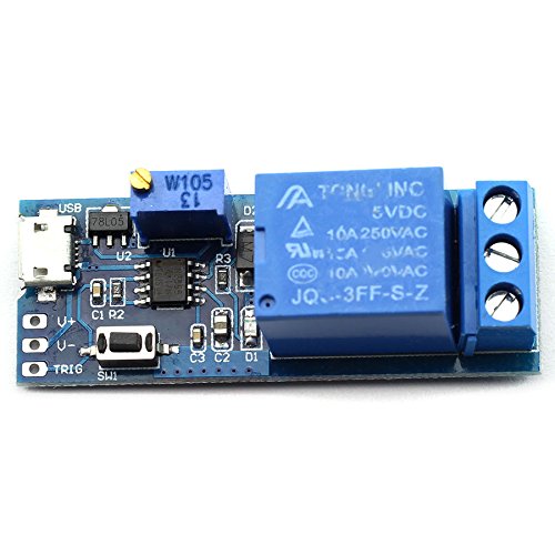
Figure 3.2: Top view of the relay board, showing the Micro USB port, potentiometer, and relay.
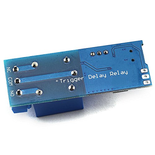
Figure 3.3: Bottom view of the relay board, showing the 'Delay Relay' and 'Trigger' labels on the PCB.
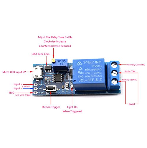
Figure 3.4: Detailed labeled diagram of the relay board components and connection points.
- Micro USB Input 5V: Power input via Micro USB cable.
- Input + / Input - (6.5-30V): Alternative power input terminals for wider voltage range.
- TRIG (Low Level Trigger): External trigger input terminal.
- Button Trigger (SW1): On-board light-touch button for manual triggering.
- Potentiometer (W105): Used to adjust the delay time from 0 to 24 seconds. Clockwise rotation increases delay, counter-clockwise reduces it.
- Relay: The switching component.
- Public COM: Common terminal for the relay output.
- Normally Open (NO): Relay output terminal that is open (disconnected from COM) when the relay is de-energized.
- Normally Closed (NC): Relay output terminal that is closed (connected to COM) when the relay is de-energized.
- Light On When Triggered: Indicator LED that illuminates when the relay is active.
4. Specifications
| Specification | Value |
|---|---|
| Work Voltage | 5V-30V DC |
| Output Load (AC) | 0-220V, 10A |
| Output Load (DC) | 0-30V, 10A |
| Delay Time Range | 0-24 seconds (adjustable) |
| Input Modes | Micro USB, Solder Terminal (Input + / Input -) |
| Trigger Modes | External Low Pulse Signal (TRIG), On-board Button (SW1) |
| Dimensions | 5.4 x 1.9 x 1.8 cm (2.13 x 0.75 x 0.71 inches) |
| Item Model Number | 4350280271 |
| Contact Material | Silver |
| Contact Type | Normally Closed (NC) |
| Mounting Type | Surface Mount |
5. Setup
Follow these steps to set up your DZS Elec Delay Trigger Relay Board:
- Power Supply Connection:
- For 5V power, connect a Micro USB cable to the Micro USB port on the board.
- Alternatively, for 6.5V-30V power, connect the positive supply to the 'Input +' terminal and the negative supply to the 'Input -' terminal. Ensure correct polarity.
- Load Connection:
- Identify the 'Public COM', 'Normally Open (NO)', and 'Normally Closed (NC)' terminals.
- Connect your load (e.g., light, motor) in series with the 'Public COM' and either the 'NO' or 'NC' terminal, depending on your desired default state.
- For a load that should be OFF by default and turn ON after triggering, connect it between 'Public COM' and 'NO'.
- For a load that should be ON by default and turn OFF after triggering, connect it between 'Public COM' and 'NC'.
- Delay Time Adjustment:
- Use a small screwdriver to rotate the potentiometer (labeled W105 in Figure 3.4).
- Rotate clockwise to increase the delay time (up to 24 seconds).
- Rotate counter-clockwise to decrease the delay time (down to 0 seconds).
- Trigger Input:
- For external triggering, connect a low pulse signal to the 'TRIG' terminal.
- For manual triggering, use the on-board light-touch button (SW1).
6. Operating Modes
The relay board operates in a specific sequence based on power and trigger signals:
- Initial State (Power On, No Trigger):
- Upon applying power to the module, the relay is de-energized.
- The 'Normally Open (NO)' terminal is disconnected from the 'Common (COM)' terminal.
- The 'Normally Closed (NC)' terminal is connected to the 'Common (COM)' terminal.
- Triggered State:
- When a low pulse signal is provided to the 'TRIG' terminal or the on-board button is pressed, the relay energizes.
- The indicator light illuminates.
- The 'Normally Open (NO)' terminal connects to the 'Common (COM)' terminal.
- The 'Normally Closed (NC)' terminal disconnects from the 'Common (COM)' terminal.
- Delay and Reset:
- After the set delay time (0-24 seconds) has elapsed, the relay de-energizes automatically.
- The indicator light turns off.
- The relay returns to its initial state (NO disconnected from COM, NC connected to COM).
7. Applications
This delay relay board is suitable for a variety of applications, including:
- Security alarm delay systems.
- Timed control of building electric lights (on/off).
- Delay conduction for on-board equipment in vehicles to prevent excessive current during startup.
- Sequential startup of multiple devices to avoid over-current issues when starting simultaneously.
- General circuit control and industrial automation requiring timed operations.
8. Maintenance
The DZS Elec Delay Trigger Relay Board is designed for reliable operation with minimal maintenance. To ensure longevity and proper function:
- Keep the board clean and free from dust and moisture.
- Avoid exposing the board to extreme temperatures or direct sunlight.
- Ensure all connections are secure and free from corrosion.
- Do not exceed the specified voltage and current ratings for the input and output.
9. Troubleshooting
If you encounter issues with your relay board, consider the following troubleshooting steps:
- No Power: Verify that the power supply is connected correctly and providing the specified voltage (5V via Micro USB or 6.5-30V via terminals). Check for loose connections.
- Relay Not Triggering: Ensure the trigger signal is correctly applied to the 'TRIG' terminal (low pulse) or that the on-board button is functioning. Check for proper wiring of external trigger sources.
- Incorrect Delay Time: Adjust the potentiometer (W105) to set the desired delay. Ensure it is not at its minimum or maximum limit if an intermediate delay is required.
- Load Not Switching: Check the wiring of your load to the 'COM', 'NO', and 'NC' terminals. Ensure the load's voltage and current requirements do not exceed the relay's specifications (AC 0-220V 10A, DC 0-30V 10A).
- Intermittent Operation: Check for strong electromagnetic interference in the environment. The board has anti-jamming features, but excessive noise can still affect performance. Ensure stable power supply.
10. Warranty and Support
For warranty information or technical support, please contact DZS Elec directly through their official channels or the retailer from whom the product was purchased. Keep your purchase receipt for warranty claims.