AllAboutAdapters IP-P2a
User Manual
AllAboutAdapters 2-Outlet Remote Power Reboot Controller with Web GUI (Model: IP-P2a)
Product Overview
The AllAboutAdapters 2-Outlet Remote Power Reboot Controller (Model: IP-P2a) is a professional network-controlled power switch designed for remote and central management of AC power distribution. It allows administrators to control power to connected devices via LAN, WAN, or the internet, offering features such as distant power reboot, equipment power on/off control, web administration, power event scheduling, and auto-reboot for failed network devices through auto-ping setup.
Each AC power outlet can be independently controlled (on, off, or power cycle) for immediate or time-delayed reboots and scheduled power events. This device is designed to eliminate the need for on-site technical personnel for simple power cycling tasks. It features high voltage resistance and a 12.0 Amp total maximum current output. The unit is 1U rack mount ready; rack mounting ears are sold separately.
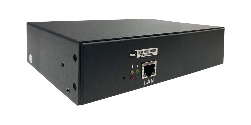
Figure 1: Front and rear view of the IP-P2a Remote Power Controller, showing the Ethernet port and power outlets.

Figure 2: Rear panel of the IP-P2a, highlighting the two independently controllable AC power outlets and the main power switch.
Key Features
- Remote Power Control: Manage AC power distribution through LAN, WAN, or the internet.
- Independent Outlet Control: Each of the two AC power outlets can be independently powered on, off, or power cycled.
- Web-Based Administration: Intuitive web GUI for configuration and control.
- Auto-Ping Functionality: Monitors networked devices and can trigger auto-reboot upon ping failure.
- Power Event Scheduling: Schedule power on/off or reboot events periodically or at specific times.
- Timed Delay Sequencing: Supports power cycling sequences with timed delays for each outlet.
- Alert Notifications: Configurable warning alerts via email, SMS, or SNMP trap.
- User Access Control: Assign permissions for multiple users to access specific power outlets.
- Overload Protection: Built-in 12-Amp circuit breaker for protection.
- Rack Mountable: 1U rack mount ready (ears sold separately).

Figure 3: Overview of the IP-P2a's advanced features, including remote control, scheduling, and various alert mechanisms.
Setup and Installation
Package Contents
- AllAboutAdapters IP-P2a Remote Power Reboot Controller
- Power Cord
- Ethernet Cable
- (Optional) Rack Mounting Ears (sold separately)
Physical Installation
- Placement: Position the IP-P2a in a stable, well-ventilated area, away from direct sunlight and excessive heat or moisture. If rack mounting, ensure proper airflow within the rack.
- Power Connection: Connect the provided power cord to the IP-P2a's power inlet and then to a standard AC power outlet. Ensure the main ON/OFF switch on the unit is in the OFF position before connecting.
- Network Connection: Connect an Ethernet cable from the IP-P2a's LAN port to your network router, switch, or directly to a PC for initial setup.
- Device Connection: Plug the power cords of the devices you wish to control into the AC outlets (1 and 2) on the IP-P2a.
- Power On: Flip the main ON/OFF switch on the IP-P2a to the ON position. The power indicator light should illuminate.

Figure 4: Connection diagram illustrating how the IP-P2a integrates into a network for remote power management.

Figure 5: Detailed component identification of the IP-P2a unit.
Initial Network Configuration
By default, the IP-P2a may obtain an IP address via DHCP. To access the web GUI:
- Find IP Address: Use a network scanner tool or check your router's DHCP client list to find the IP address assigned to the IP-P2a. Alternatively, some units may have a default static IP (refer to specific product documentation if DHCP fails).
- Access Web GUI: Open a web browser and enter the IP address of the IP-P2a in the address bar (e.g., http://192.168.1.10).
- Login: Enter the default username and password (typically 'admin' for both, or as specified in the device's label/documentation).
It is highly recommended to change the default password immediately after the first login for security purposes.
Operating Instructions
Web GUI Overview
The intuitive web GUI provides comprehensive control and monitoring capabilities. Key sections typically include:
- Monitor: View current status of outlets.
- System: General system settings, network configuration.
- Account: User management and password changes.
- Time: Time and date settings for scheduling.
- Event: Event logs and alert configurations.
- Upgrade: Firmware upgrade utility.

Figure 6: Web GUI interface for power control and scheduling.
Controlling Power Outlets
From the web GUI, navigate to the 'Monitor' or 'Power' section. You will see controls for each outlet (Port 1 and Port 2).
- Power On: Click the 'ON' button for the desired outlet.
- Power Off: Click the 'OFF' button for the desired outlet.
- Reboot (Power Cycle): Click the 'Reboot' button. This will turn the outlet off, wait for a configurable delay, and then turn it back on.
- Timed Delay: Configure power-on or power-off delays in seconds or minutes for sequential power cycling.
Scheduling Power Events
The 'Schedule' section allows you to set up automated power events.
- Select the desired outlet.
- Choose the action (ON, OFF, REBOOT).
- Set the frequency (e.g., daily, weekly, monthly) and specific time.
- Save the schedule.
Auto-Ping Setup
Configure the auto-ping feature to monitor network devices and automatically reboot them if they become unresponsive.
- Navigate to the 'Auto-Ping' section.
- Enter the IP address or domain name of the device to monitor.
- Set the ping interval and the number of failed pings before an action is triggered.
- Select the action to perform (e.g., reboot the associated outlet).
- Save the settings.
Alert Notifications
The IP-P2a can send alerts for critical power conditions or ping failures.
- Email Alerts: Configure SMTP server settings, sender, and recipient email addresses in the 'Email Server' section.
- SMS Text Messages: Set up SMS gateway details if supported by your service provider in the 'SMS' section.
- SNMP Trap: Configure SNMP settings and trap destinations in the 'SNMP' section for integration with network management systems.

Figure 7: Web GUI configuration pages for network, email, SMS, and SNMP settings.
Maintenance
- Cleaning: Periodically clean the exterior of the unit with a soft, dry cloth. Do not use liquid cleaners or aerosols.
- Ventilation: Ensure that the ventilation openings are not blocked to prevent overheating.
- Firmware Updates: Check the manufacturer's website periodically for firmware updates. Firmware updates can provide new features, bug fixes, and security enhancements. Follow the instructions provided with the firmware update carefully.
- Cable Management: Ensure all power and network cables are securely connected and not under strain.
Troubleshooting
| Problem | Possible Cause | Solution |
|---|---|---|
| Device does not power on. | No power to the unit; Main ON/OFF switch is off. | Check power cord connection and wall outlet. Ensure the main ON/OFF switch is in the ON position. |
| Cannot access web GUI. | Incorrect IP address; Network connectivity issue; Firewall blocking access. | Verify the IP address of the IP-P2a. Check Ethernet cable connection. Ensure your computer is on the same network segment. Temporarily disable firewalls for testing. |
| Outlets do not respond to commands. | Device is offline; Overload protection tripped. | Check network connection. Verify the IP-P2a is powered on. Check the 12-Amp circuit breaker/protector on the unit and reset if tripped. |
| Auto-ping not working. | Incorrect IP/domain; Network issues; Auto-ping not enabled. | Verify the target IP address/domain is correct and reachable from the IP-P2a's network. Ensure auto-ping is enabled and configured correctly in the web GUI. |
Specifications
| Feature | Detail |
|---|---|
| Model Number | IP-P2a |
| Brand | AllAboutAdapters |
| Outlets | 2 x AC Power Outlets (Independently controllable) |
| Max Current Output | 12.0 Amps (Total) |
| Input Voltage | AC 100V-240V |
| Operation Mode | ON-NONE-ON |
| Connector Type | Ethernet (RJ45) |
| Contact Type | Normally Open |
| Terminal | Screw |
| Circuit Type | 2-way |
| Actuator Type | Push Button |
| Contact Material | Copper |
| International Protection Rating | IP54 |
| Item Weight | 3 Pounds |
| Rack Mount | 1U Rack Mount Ready (Ears sold separately) |
Warranty and Support
For warranty information and technical support, please contact AllAboutAdapters directly. Details are typically available on their official website or through the retailer where the product was purchased.
Please retain your proof of purchase for warranty claims.