1. Product Overview
The Heschen SSR-40DD is a single-phase DC to DC Solid State Relay designed for switching DC loads. It offers reliable, fast switching without mechanical contacts, making it suitable for various industrial control applications. This manual provides essential information for the safe and effective installation and operation of the SSR-40DD.
Key Features:
- Load Current: 40A
- Load Voltage: 24-220VDC
- Control Voltage: 4-32VDC
- LED working instructions for status indication
- CE ISO9001 listed for quality assurance
- Wide input voltage range, control current less than or equal to 10 mA
- No mechanical contacts, long service life, high reliability
- Rapid switching speed with minimal radio frequency (RF) interference
- Built-in RC (Resistor-Capacitor) absorption circuit to protect against inrush current during startup
- Opto-isolation between input and output circuits, and insulation withstand voltage of 2500V
- Compact design with internal epoxy resin potting for enhanced resistance to vibration, moisture, and corrosion
2. Safety Information
Read all instructions carefully before installation and operation. Failure to follow these safety guidelines may result in electric shock, fire, or serious injury.
- Electrical Hazard: Always disconnect power before installing or servicing the relay.
- Qualified Personnel: Installation and maintenance should only be performed by qualified electricians or technicians.
- Voltage and Current Ratings: Do not exceed the specified load voltage (24-220VDC) or load current (40A).
- Heat Dissipation: Solid state relays generate heat during operation. Adequate heat sinking is mandatory to prevent overheating and premature failure.
- Proper Wiring: Ensure all connections are secure and correctly polarized (+/-) as indicated on the relay.
- Inductive Loads: For inductive loads (motors, transformers, solenoids), a freewheeling diode must be added in parallel with the load to protect the relay from back EMF.
- Environmental Conditions: Operate the relay within the specified ambient temperature range (-20°C to +75°C).
3. Dimensions and Physical Characteristics

Figure 3.1: Heschen SSR-40DD Solid State Relay with detailed dimensions. The relay measures approximately 45mm (1.77") in height, 45.5mm (1.79") in width, and 26mm (1.02") in depth. Mounting holes are 4mm (0.15") in diameter.
- Size (L x W x H): 60mm x 45.5mm x 26mm
- Weight: 95g
- Mounting Type: Bolting (Screw Mount)
- Material: Metal baseplate for heat dissipation.
4. Installation and Wiring
4.1 Heat Dissipation Requirements
Heat generated by the relay during operation must be dissipated through its metal baseplate. Ensure the relay is tightly mounted to a suitable heat sink. Thermal conductive grease must be applied to the contact surface between the relay and the heat sink to ensure efficient heat transfer.

Figure 4.1: Illustrated steps for proper heat sink installation. 1. Wipe the back of the SSR clean. 2. Use a brush to spread thermal grease. 3. Apply thermal grease evenly. 4. Securely fasten the relay to the heat sink.
4.2 Wiring Diagram
Connect the control voltage to terminals +3 and +4, and the load to terminals +1 and +2. Observe correct polarity for both control and load circuits.
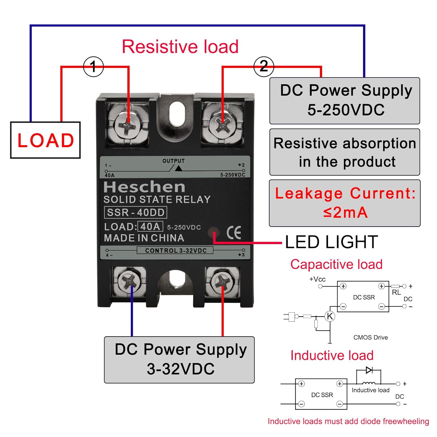
Figure 4.2: Wiring diagram for the SSR-40DD. The control input (3-32VDC) connects to terminals +3 and +4. The DC load (5-250VDC) connects to terminals +1 and +2. An LED light indicates operation. For inductive loads, a freewheeling diode is required.
- Control Input: Connect your DC control signal (4-32VDC) to terminals labeled +3 and +4. Ensure correct polarity.
- Load Output: Connect your DC load (24-220VDC, up to 40A) to terminals labeled +1 and +2. Ensure correct polarity.
- LED Indicator: The built-in LED will illuminate when the control voltage is applied, indicating the relay is active.
- Inductive Loads: When switching inductive loads such as motors or solenoids, it is critical to install a freewheeling diode in parallel with the load. This diode protects the SSR from voltage spikes generated by the inductive load when it is switched off.
5. Operating Instructions
The SSR-40DD operates by receiving a DC control signal to switch a higher power DC load. When the control voltage (4-32VDC) is applied to the input terminals, the internal circuitry activates, allowing current to flow through the load terminals. When the control voltage is removed, the relay deactivates, stopping current flow to the load.
- Activation: Apply a DC voltage between 4V and 32V to the control terminals (+3 and +4).
- Deactivation: Remove the DC voltage from the control terminals.
- Status Indication: The integrated LED will light up when the control signal is present and the relay is in the ON state.
6. Load Current Calculation and Selection
To ensure proper operation and longevity of the solid state relay, it is essential to select a relay with an appropriate current rating for your specific load. The required current capacity of the SSR depends on the type of load (resistive or inductive).

Figure 6.1: Current calculation guide for SSR selection. For resistive loads, multiply equipment current by 2. For inductive loads, multiply by 6. Includes a table with recommended SSR models based on load type and current.
Calculation Method:
- Resistive Loads: For loads like electric heating elements, incandescent lamps, or resistors, multiply the equipment's rated current by a coefficient of 2.
Example: A heater with a rated current of 15A (resistive load) requires an SSR of 15A * 2 = 30A. Choose a 30A solid state relay. - Inductive Loads: For loads such as motors, transformers, capacitors, solenoid valves, or air conditioners, multiply the equipment's rated current by a coefficient of 6.
Example: A motor with a rated current of 15A (inductive load) requires an SSR of 15A * 6 = 90A. Choose a 100A solid state relay.
Always select an SSR with a current rating equal to or greater than the calculated value to ensure safe and reliable operation.
7. Specifications
| Parameter | Value |
|---|---|
| Model | SSR-40DD |
| Load Current | 40 Amps |
| Load Voltage | 24-220VDC (Max 250VDC) |
| Control Voltage | 4-32VDC |
| Minimum Control Current | 5mA |
| Maximum Control Current | 20mA |
| Guaranteed Turn-On Voltage | 3.5VDC |
| Guaranteed Turn-Off Voltage | 1.5VDC |
| Insulation Resistance | 100MΩ/500VDC |
| Leakage Current (OFF State) | ≤2mA rms |
| Saturation Voltage Drop (ON State) | ≤1.5V |
| Switching Response Delay | ≤10ms |
| Insulation Withstand Voltage (Input to Output) | 2500V rms |
| Insulation Withstand Voltage (Input/Output to Enclosure) | 4000V rms |
| Ambient Temperature | -20°C ~ +75°C |
| Mounting Type | Bolting (Screw Mount) |
| Connector Type | Screw |
| Contact Type | Normally Open |
| Operation Mode | Automatic |
| Wattage | 8800 watts (Calculated for 220VDC, 40A) |
| Specification Met | CE, ISO9001 |
Note: Specifications are subject to change without prior notice.
8. Maintenance
The Heschen SSR-40DD is designed for long-term, reliable operation with minimal maintenance. However, periodic checks can help ensure optimal performance and extend its lifespan.
- Visual Inspection: Periodically inspect the relay and its connections for any signs of damage, loose wiring, or discoloration due to overheating.
- Cleanliness: Ensure the relay and heat sink are free from dust and debris, which can impede heat dissipation. Use a soft, dry cloth for cleaning.
- Tightness of Connections: Verify that all screw terminals are securely tightened to prevent arcing and poor contact.
- Heat Sink Performance: Confirm that the heat sink is not obstructed and that the relay's operating temperature remains within acceptable limits. Excessive heat can significantly reduce the relay's lifespan.
9. Troubleshooting
If you encounter issues with your SSR-40DD, refer to the following troubleshooting guide:
| Problem | Possible Cause | Solution |
|---|---|---|
| Relay does not turn ON (LED off) | No control voltage; Control voltage too low; Incorrect control polarity; Faulty control circuit. | Check control voltage (must be 4-32VDC); Verify control polarity (+3 to positive, +4 to negative); Test control circuit. |
| Relay turns ON but load does not activate | No load voltage; Load voltage too low; Incorrect load polarity; Open circuit in load; Faulty load. | Check load voltage (must be 24-220VDC); Verify load polarity (+1 to positive, +2 to negative); Inspect load wiring; Test the load independently. |
| Relay overheats | Insufficient heat sinking; Overcurrent condition; High ambient temperature. | Ensure proper heat sink installation and thermal grease application; Verify load current does not exceed 40A; Improve ventilation around the relay. |
| Relay fails prematurely | Overcurrent; Overvoltage spikes (especially with inductive loads); Inadequate heat dissipation; Incorrect wiring. | Review load current calculation and ensure SSR rating is sufficient; Install freewheeling diode for inductive loads; Ensure proper heat sinking; Double-check all wiring. |
| Relay remains ON (does not turn OFF) | Control voltage not completely removed; Control voltage above turn-off threshold (1.5VDC); Internal fault. | Ensure control voltage drops below 1.5VDC when off; Disconnect control wires to confirm relay state; If problem persists, the relay may be faulty. |
If troubleshooting steps do not resolve the issue, contact Heschen customer support or a qualified technician.