1. Important Safety Information
Read all instructions carefully before installation and use. Failure to follow these instructions may result in property damage, serious injury, or death. If you do not understand these instructions, or have doubts about the safety of the installation, contact a qualified installer.
- Weight Capacity: This mount is designed for flat panel displays up to 32 inches. Do not exceed the maximum weight capacity specified by the manufacturer.
- Wall Structure: Ensure the mounting surface can safely support the combined weight of the equipment and hardware. Use appropriate fasteners for the wall type (wood stud, concrete, brick, etc.).
- Professional Installation: For optimal safety, professional installation is recommended.
- Moving Parts: Exercise caution when adjusting the tilt mechanism to avoid pinching or injury.
2. Package Contents
Verify that all components are present and undamaged before proceeding with installation. If any parts are missing or damaged, do not attempt to install and contact customer support.
- Flat Panel Wall Mount (FTR100)
- Mounting Hardware Kit (screws, washers, anchors - specific contents may vary)
- Installation Instructions (this document)
3. Setup and Installation
This section provides step-by-step instructions for mounting your Chief FTR100 Tilting Hardware Mount.
3.1 Pre-Installation Checks
- Identify the desired mounting location. Ensure there are no hidden electrical wires or plumbing.
- Confirm the wall type (wood stud, concrete, brick) and select appropriate mounting hardware.
- Measure the VESA mounting pattern on your flat panel display to ensure compatibility with the FTR100 mount.
3.2 Mounting the Wall Plate
- Position the wall plate at the desired height and mark the drilling locations. Use a level to ensure accuracy.
- Drill pilot holes according to the recommended drill bit size for your chosen fasteners and wall type.
- Secure the wall plate to the wall using the provided mounting hardware. Ensure all screws are tightened securely.
3.3 Attaching the Display to the Mount
- Attach the display brackets to the back of your flat panel display using the appropriate screws from the hardware kit. Ensure they are securely fastened.
- Carefully lift the display and hook the display brackets onto the wall plate. The FTR100 utilizes a Q-Latch mounting system for secure attachment.
- Engage the Q-Latch mechanism to lock the display onto the wall plate. Refer to the specific latching instructions provided with the hardware kit.
- The mount can be used in either a horizontal or vertical orientation, depending on your display and application.
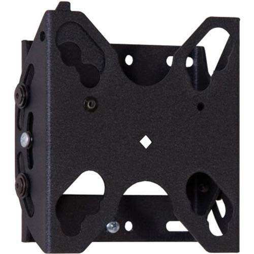
Figure 1: Chief FTR100 Tilting Hardware Mount. This image shows the overall design of the mount, including the wall plate and display brackets, ready for installation.
4. Operating the Mount
The Chief FTR100 mount allows for tilting adjustments to achieve optimal viewing angles.
4.1 Tilting the Display
Once the display is securely mounted, you can adjust its tilt angle. The FTR100 offers a maximum tilt angle of 15 degrees.
- Gently grasp the top or bottom edge of the display.
- Carefully push or pull the display to achieve the desired tilt angle. The mount is designed to hold the position once set.
- Avoid excessive force when tilting. If the display does not move smoothly, check for obstructions or consult the troubleshooting section.
5. Maintenance
Regular maintenance helps ensure the longevity and safe operation of your mount.
- Cleaning: Use a soft, dry cloth to clean the mount. Avoid abrasive cleaners or solvents that could damage the finish.
- Periodic Checks: Periodically inspect all mounting screws and connections to ensure they remain tight and secure. Re-tighten if necessary.
- Moving Parts: The tilting mechanism is designed for smooth operation. If it becomes stiff, do not apply lubricants unless specifically recommended by Chief Mfg.
6. Troubleshooting
This section addresses common issues you might encounter with your Chief FTR100 mount.
- Display is not level:
- Check the wall plate installation. Ensure it was installed using a level.
- Verify that the display brackets are evenly attached to the back of the display.
- Difficulty tilting the display:
- Ensure no cables are obstructing the tilting mechanism.
- Confirm the display weight is within the specified limits for the mount.
- Mount feels loose:
- Immediately remove the display.
- Re-tighten all wall plate and display bracket screws. If the issue persists, consult a professional installer.
7. Specifications
Detailed technical specifications for the Chief FTR100 Tilting Hardware Mount.
| Feature | Specification |
|---|---|
| Brand | Chief |
| Model Number | FTR100 |
| Item Weight | 2.66 pounds |
| Product Dimensions | 2.87 x 6.02 x 9.29 inches |
| Mounting Type | Wall Mount |
| Movement Type | Tilt |
| Material | Metal |
| Color | Black |
| Maximum Tilt Angle | 15 Degrees |
| Compatible Devices | Monitor (Flat Panel Display up to 32") |
| Special Features | Tilting, Q-Latch Mounting System, Horizontal/Vertical Use |
8. Warranty and Support
For warranty information, technical support, or to inquire about replacement parts, please contact Chief Manufacturing directly. Refer to the official Chief website or your purchase documentation for current contact details and warranty terms.
Manufacturer: Chief Mfg.
Website: www.legrandav.com/products/chief (This is a common URL for Chief products, please verify with official documentation)