
1. Product Overview
The WINGONEER TTL to RS485 Adapter Module is designed for converting TTL serial signals to RS485 signals. This module offers full compatibility with both 3.3V and 5.0V power supplies and signal levels, making it versatile for various microcontroller applications. It facilitates robust and long-distance communication between microcontrollers and RS485 devices, even in industrial or harsh outdoor environments.
Key features include signal indicator LEDs for RXD and TXD, industrial-grade chip design with strong anti-interference capabilities, and effective lightning protection. Its compact size and standard 2.54mm pitch design simplify integration and secondary development.
2. Features
- Voltage Compatibility: Fully compatible with 3.3V and 5.0V power supplies and signal levels.
- Operating Temperature: Wide range from -40°C to +85°C.
- Compact Design: Dimensions of 42.8mm × 15.22mm × 0.8mm.
- Signal Indicators: RXD and TXD signal indicator LEDs to monitor transmit/receive status.
- Long Transmission Distance: Supports transmission up to 800 meters (recommended), tested up to 850 meters. For distances exceeding 800 meters, a repeater is advised.
- Industrial Grade: Features an imported industrial-grade chip design with strong anti-interference capability and effective lightning protection.
- Easy Integration: 0.8mm thick PCB with semi-hole processing, suitable for integration into other boards and easy terminal soldering.
- Secondary Development: Standard 2.54mm pitch design for convenient prototyping and secondary development.
- Termination Resistor: Integrated 120-ohm termination resistor, selectable via a shorting jumper (R0), for stable long-distance data transfer.
- Multi-Machine Support: Supports multi-machine communication, enabling up to 128 devices on the bus.
- Hot-Swappable: Designed to be hot-swappable, preventing signal interruption during connection or disconnection.
- Enhanced Anti-Interference: Wide copper area on the PCB to prevent signal interference.
- Automatic Flow Control: Hardware automatic flow control for reliable data transfer.
3. Module Layout and Pinout
The module features clearly labeled pins for easy connection. Below is an image illustrating the top view of the module with its pinout.

Figure 1: Top view of the WINGONEER TTL to RS485 Adapter Module, highlighting the GND, RXD, TXD, VCC, A+, and B- pins, along with various electronic components and indicator LEDs.
The bottom side of the module displays the model identifier.
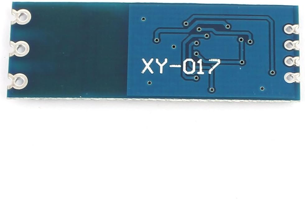
Figure 2: Bottom view of the module, showing the model number 'XY-017' printed on the PCB.
Pin Description:
- GND: Ground connection.
- RXD: Receive Data (TTL level input from microcontroller).
- TXD: Transmit Data (TTL level output to microcontroller).
- VCC: Power supply input (3.3V or 5V, matching your microcontroller's logic level).
- A+: RS485 differential data line A.
- B-: RS485 differential data line B.
4. Setup Instructions
4.1 Power Supply Connection
Connect the VCC pin to your microcontroller's 3.3V or 5V power supply output, ensuring it matches the logic level of your microcontroller. Connect the GND pin to the common ground of your system.
4.2 TTL Serial Connection
- Connect the TXD pin of your microcontroller to the RXD pin of the RS485 module.
- Connect the RXD pin of your microcontroller to the TXD pin of the RS485 module.
4.3 RS485 Bus Connection
Connect the A+ and B- pins of the module to the corresponding A+ and B- lines of your RS485 bus. Ensure consistent polarity across all devices on the bus.
4.4 Termination Resistor (R0)
The module includes a 120-ohm termination resistor. For long-distance communication or in bus configurations with multiple devices, termination resistors are crucial to prevent signal reflections. To enable the internal 120-ohm termination resistor, short the R0 jumper pad on the module. Typically, only the devices at the two ends of the RS485 bus require termination.
5. Operating Instructions
The WINGONEER TTL to RS485 Adapter Module operates in half-duplex mode, meaning data can be transmitted in one direction at a time. The module features hardware automatic flow control, eliminating the need for external control signals (like DE/RE pins) from the microcontroller to manage data direction.
5.1 Data Transmission
When your microcontroller sends data via its TX pin (connected to the module's RXD), the module automatically converts it to RS485 differential signals and transmits it on the A+ and B- lines. The TXD indicator LED on the module will illuminate during transmission.
5.2 Data Reception
When RS485 signals are received on the A+ and B- lines, the module automatically converts them to TTL serial signals and outputs them via its TXD pin (connected to your microcontroller's RX pin). The RXD indicator LED on the module will illuminate during reception.
5.3 Software Configuration
On your microcontroller, configure the UART (Universal Asynchronous Receiver-Transmitter) for the desired baud rate, data bits, parity, and stop bits. Since the module handles flow control automatically, no specific RS485 control pin (like DE/RE) needs to be managed in your software.
6. Maintenance
- Storage: Store the module in a dry, anti-static environment when not in use.
- Handling: Handle the module with care to avoid physical damage to components or solder joints.
- Cleaning: If necessary, gently clean the module with a soft, dry brush or compressed air. Avoid using liquids or solvents.
- Temperature: Operate and store the module within its specified temperature range (-40°C to +85°C) to ensure optimal performance and longevity.
7. Troubleshooting
- No Communication:
- Verify all wiring connections (GND, VCC, RXD, TXD, A+, B-).
- Ensure the power supply voltage (3.3V or 5V) matches the module's and microcontroller's logic levels.
- Check if the microcontroller's UART is correctly configured (baud rate, data bits, parity, stop bits).
- Confirm that the RS485 bus is properly terminated, especially for long cables or multi-drop networks.
- Intermittent Communication:
- Check for excessive cable length or poor cable quality.
- Ensure proper termination resistors are used at both ends of the bus.
- Inspect for sources of electromagnetic interference (EMI) near the communication lines.
- Indicator LEDs Not Lighting Up:
- If neither RXD nor TXD LED lights up, check the VCC and GND connections.
- If only one LED lights up, verify data flow from the corresponding side (e.g., if TXD LED doesn't light up, check if the microcontroller is sending data).
- Incorrect Data Received:
- Double-check the baud rate and other UART settings.
- Ensure consistent data format between transmitting and receiving devices.
- Verify RS485 A+ and B- polarity.
8. Specifications
| Specification | Value |
|---|---|
| Model Number | XY-017 |
| Dimensions | 42.8mm × 15.22mm × 0.8mm |
| Operating Voltage | 3.3V / 5V (selectable) |
| Signal Voltage | 3.3V / 5V (compatible) |
| Operating Temperature | -40°C to +85°C |
| Transmission Distance | Up to 800m (recommended), 850m (tested) |
| Bus Capacity | Up to 128 devices |
| Termination Resistor | 120 Ohm (selectable via R0 jumper) |
| PCB Thickness | 0.8mm |
| Connector Type | Pin headers (2.54mm pitch) |
| Product Weight | 0.02 kg |
9. Warranty and Support
Specific warranty information for this product is not provided in the available data. For any technical support or warranty inquiries, please refer to the retailer or manufacturer's official channels where the product was purchased.