1. Introduction
This manual provides detailed instructions for the WINGONEER SW-18010P Vibration Sensor Module. This module is designed to detect vibrations and output a digital signal, making it suitable for various applications such as theft alarms, intelligent car systems, and earthquake alarms. It features a comparator output for a clean signal and strong driving capability.
2. Product Overview
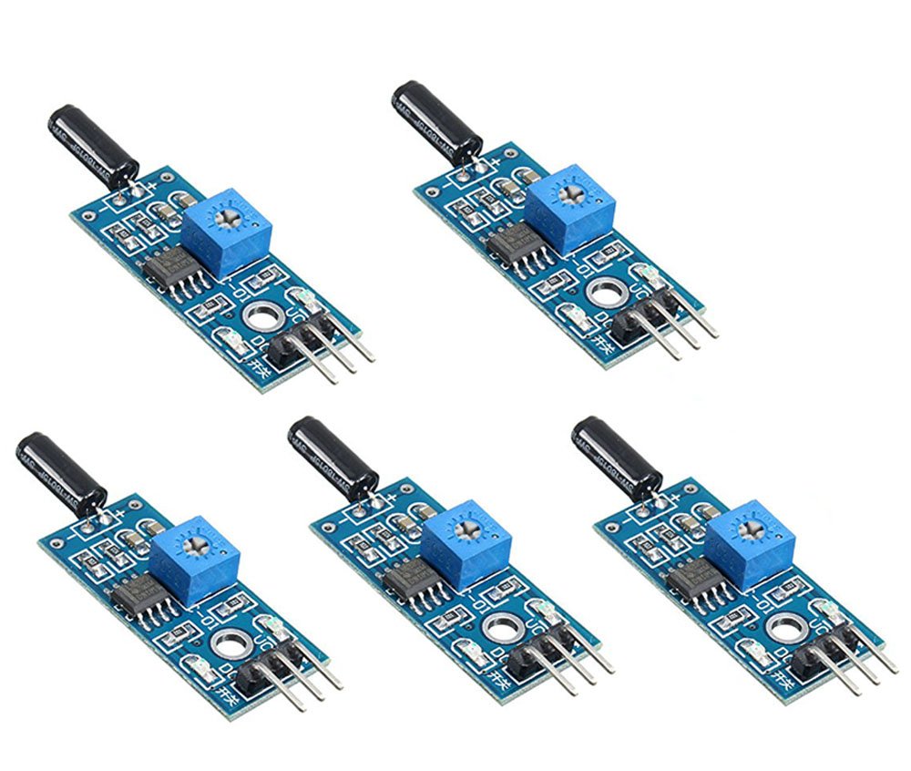
This image shows the top view of the WINGONEER SW-18010P Vibration Sensor Module, highlighting its components including the SW-18010P sensor, LM393 comparator, potentiometer, and pin headers.
The WINGONEER SW-18010P Vibration Sensor Module is an open-type vibration sensor. Key features include:
- Comparator output for a clean, strong signal (over 15mA).
- Wide operating voltage range of 3V to 5V.
- Digital switch output (0 and 1).
- Fixed bolt holes for convenient installation.
- Compact PCB size: 3.1 cm x 1.4 cm.
- Utilizes the LM393 wide voltage comparator.
- Incorporates the SW-18010P Vibration sensor.
3. Setup and Connections
To set up the vibration sensor module, connect it to your microcontroller or circuit board using the provided pin headers. Ensure correct polarity for power connections.

This diagram illustrates the pin assignments for the WINGONEER SW-18010P Vibration Sensor Module. VCC is for positive power supply, GND for ground, and DO for digital signal output. AO (Analog Output) is not used for this module's function.
- VCC: Connect to the positive power supply (3V to 5V).
- GND: Connect to the ground of your power supply.
- DO (Digital Output): Connect to a digital input pin on your microcontroller to read the vibration status.
- AO (Analog Output): This pin is not used for the digital switch functionality of this module.
The module includes a potentiometer (blue component) that can be adjusted to set the sensitivity threshold for vibration detection.
4. Operating Instructions
The SW-18010P vibration sensor module operates as a digital switch. Its output state changes based on the presence of vibration.
- No Vibration: When the product is not experiencing shock or vibration, the internal vibration switch is in an OFF state. The DO (Digital Output) pin will output a HIGH signal. The green indicator LED on the module will not illuminate.
- Vibration Detected: When the product experiences shock or vibration, the internal vibration switch momentarily turns ON. The DO (Digital Output) pin will output a LOW signal. The green indicator LED on the module will illuminate.
You can directly connect the DO pin to a microcontroller's digital input to detect these HIGH and LOW states, thereby determining if vibration has occurred.
5. Specifications

This image displays the physical dimensions of the WINGONEER SW-18010P Vibration Sensor Module, indicating a length of 32mm and a width of 14mm.
| Specification | Value |
|---|---|
| Operating Voltage | 3V to 5V |
| Output Type | Digital Switch Output (0 and 1) |
| Comparator | LM393 Wide Voltage Comparator |
| Sensor Type | SW-18010P Vibration Sensor |
| PCB Dimensions | 3.1 cm x 1.4 cm (approx. 32mm x 14mm) |
| Output Drive Capability | Greater than 15mA |
| Item Weight | 7 ounces (for 5 modules) |
| Model Number | JT0682 |
6. Maintenance
The WINGONEER SW-18010P Vibration Sensor Module is a low-maintenance electronic component. To ensure its longevity and reliable operation:
- Keep the module clean and free from dust and debris.
- Avoid exposing the module to extreme temperatures or humidity.
- Handle with care to prevent physical damage to the sensor or PCB.
- Ensure proper ventilation if enclosed in a casing to prevent overheating.
7. Troubleshooting
If you encounter issues with your vibration sensor module, consider the following troubleshooting steps:
- No Output/Incorrect Output:
- Verify power connections (VCC and GND) are correct and within the 3V-5V operating range.
- Check the wiring to the microcontroller's digital input pin.
- Adjust the potentiometer on the module. Turn it fully counter-clockwise to maximize sensitivity.
- Ensure the vibration source is sufficient to trigger the sensor at its current sensitivity setting.
- Inconsistent Sensitivity:
- The sensitivity can vary slightly between individual modules. Fine-tune the potentiometer for each module as needed.
- Ensure the module is mounted securely and not subject to unintended vibrations.
- Microcontroller Reading Issues:
- If simply reading a digital input (HIGH/LOW) is not sufficient for your application, consider using functions like
pulseIn()on platforms like Arduino to measure the pulse length of the output signal, then trigger based on that result for more precise detection.
- If simply reading a digital input (HIGH/LOW) is not sufficient for your application, consider using functions like
8. Warranty Information
WINGONEER products are manufactured to high-quality standards. For specific warranty details, please refer to the purchase documentation or contact your retailer. Keep your proof of purchase for any warranty claims.
9. Support
For further assistance, technical support, or inquiries regarding the WINGONEER SW-18010P Vibration Sensor Module, please contact your point of purchase or refer to the official WINGONEER support channels available on their website.