1. Introduction
This manual provides comprehensive instructions for the installation, operation, and maintenance of your UHPPOTE 4 Channel Color Quad System Video Splitter, Model UT-XYL-440. This device is designed to process and display video feeds from up to four CCTV cameras simultaneously on a single monitor, offering various display modes and control options for effective surveillance monitoring.
2. Safety Information
- Ensure the device is placed on a stable, flat surface to prevent accidental falls.
- Operate the device within the specified voltage range (DC 12V) using the provided power adapter.
- Avoid exposing the unit to moisture, rain, or extreme temperatures. This device is intended for indoor use only.
- Do not open the casing or attempt to repair the unit yourself. Refer all servicing to qualified personnel.
- Maintain adequate ventilation around the unit to prevent overheating.
3. Package Contents
Please verify that all items are present in your package:
- UHPPOTE 4 Channel Color Quad System Video Splitter (UT-XYL-440)
- Infrared Remote Control
- BNC Adapters (7 pieces)
- Power Adapter (DC 12V)

Image 3.1: UHPPOTE 4 Channel Color Quad System Video Splitter, remote control, and BNC adapters.
4. Product Overview
Familiarize yourself with the components and controls of your video splitter.
4.1. Front Panel
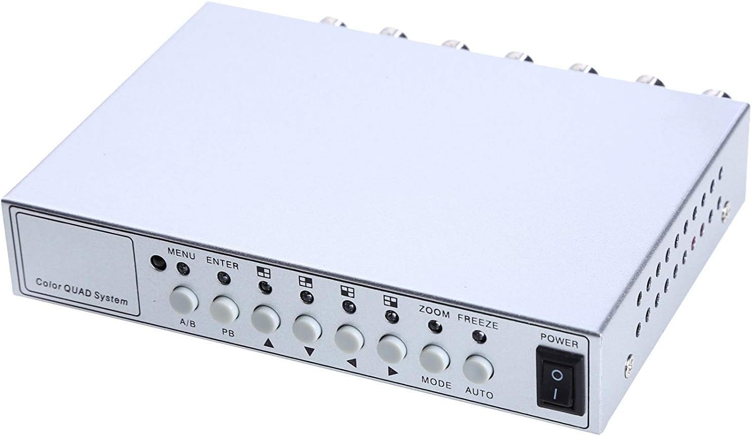
Image 4.1: Front panel controls and indicators.
- MENU: Accesses the on-screen display (OSD) menu for settings adjustment.
- ENTER: Confirms selections within the OSD menu.
- A/B: Switches between different display modes or channels.
- PB: Playback control (if connected to a VCR).
- Directional Arrows (Up/Down/Left/Right): Navigate through menu options and adjust values.
- ZOOM: Activates the digital zoom function.
- FREEZE: Freezes the current video frame.
- MODE: Cycles through various display modes (Quad, Full Screen, PIP, Dual Split).
- AUTO: Activates the auto-sequence display mode.
- POWER: On/Off switch for the unit.
4.2. Rear Panel

Image 4.2: Rear panel video input/output ports and power input.
- VIDEO 1-4: BNC inputs for connecting up to four CCTV cameras.
- VCR IN: BNC input for connecting a VCR or other recording device.
- VCR OUT: BNC output for connecting to a VCR or other recording device.
- MONITOR: BNC output for connecting to a display monitor.
- DC 12V: Power input jack for the DC 12V power adapter.
4.3. Remote Control

Image 4.3: Infrared remote control for convenient operation.
The remote control provides convenient access to all functions, mirroring the front panel controls and offering direct channel selection.
5. Setup
Follow these steps to set up your UHPPOTE Video Splitter:
- Connect Cameras: Connect your CCTV cameras to the VIDEO 1, VIDEO 2, VIDEO 3, and VIDEO 4 BNC input ports on the rear panel. Ensure secure connections.
- Connect Monitor: Connect your display monitor to the MONITOR BNC output port on the rear panel.
- Connect VCR (Optional): If you wish to record video, connect the VCR IN and VCR OUT BNC ports to your VCR or recording device.
- Connect Power: Insert the DC 12V power adapter into the DC 12V input jack on the rear panel, then plug the adapter into a standard electrical outlet.
- Power On: Press the POWER button on the front panel or remote control to turn on the unit.
6. Operating Instructions
6.1. Power On/Off
Press the POWER button on the front panel or the remote control to switch the unit on or off.
6.2. Display Modes
The unit supports various display configurations. Use the MODE button on the front panel or remote to cycle through them:
- QUAD Split Mode: Displays all four camera feeds simultaneously in a four-way split screen.
- Full Screen Mode: Displays a single camera feed in full screen. Use the directional arrows or number buttons (1-4) on the remote to select the desired camera.
- PIP (Picture-in-Picture) Mode: Displays one main camera feed with a smaller window of another camera feed. The position of the PIP window can often be adjusted via the menu.
- Dual Split Mode: Displays two camera feeds simultaneously (e.g., side-by-side or top-bottom).
- Auto Sequence Mode: Automatically cycles through full-screen views of each connected camera. Activate using the AUTO button on the front panel or remote.
6.3. Menu Navigation and Settings
To access and adjust system settings:
- Press the MENU button on the front panel or remote control. The On-Screen Display (OSD) menu will appear.
- Use the Up/Down directional arrows to navigate between menu options.
- Press ENTER to select an option or enter a sub-menu.
- Use the Left/Right directional arrows to adjust values (e.g., brightness, contrast) or change settings.
- Press MENU again to exit the menu.
Key Settings:
- Video Adjustments: Adjust Brightness, Contrast, Saturation, Hue, and Sharpness for optimal image quality.
- System Format: Select between NTSC (for North America, Japan, etc.) or PAL (for Europe, Asia, etc.) based on your region's video standard. Incorrect selection can lead to distorted or black and white images.
- Overlay Information: Configure display of Camera Title, Real Time and Date, and Alarm/Loss/Motion messages.
- Event Report: Review event logs and configure buzzer/relay output settings.
6.4. Zoom Function
In full-screen mode, press the ZOOM button on the front panel or remote to activate digital zoom. Use the directional arrows to select the area to zoom in on.
6.5. Freeze Function
Press the FREEZE (FRZ) button on the front panel or remote to pause the current video frame. Press it again to resume live video.
7. Maintenance
- Cleaning: Use a soft, dry cloth to clean the exterior of the unit. Do not use liquid or aerosol cleaners.
- Ventilation: Ensure the ventilation holes are not obstructed to prevent overheating.
- Storage: If storing the unit for an extended period, disconnect it from power and store in a cool, dry place.
8. Troubleshooting
| Problem | Possible Cause | Solution |
|---|---|---|
| No video signal on monitor |
|
|
| Distorted, black & white, or rolling image |
|
|
| Remote control not working |
|
|
| Constant buzzing sound |
|
|
9. Specifications
| Feature | Detail |
|---|---|
| Model Number | UT-XYL-440 |
| Video Inputs | 4 BNC (for cameras), 1 BNC (VCR In) |
| Video Outputs | 1 BNC (Monitor), 1 BNC (VCR Out) |
| Video Resolution | 720x480 (NTSC 60Hz), 720x576 (PAL 50Hz) |
| Display Modes | Quad Split, Full Screen, PIP, Dual Split, Auto Sequence |
| Image Adjustments | Brightness, Contrast, Saturation, Hue, Sharpness |
| Special Functions | Freeze Function, Zoom Function, Video Loss Detection, Motion Detection |
| Power Supply | DC 12V |
| Item Weight | 13.4 ounces (approx. 380g) |
| Package Dimensions | 8.54 x 6.06 x 2.4 inches (approx. 21.7 x 15.4 x 6.1 cm) |
| Remote Battery | 1 x CR2 battery (required) |
10. Warranty and Support
UHPPOTE products are designed for reliability and performance. For warranty information, technical support, or service inquiries, please refer to the contact information provided with your purchase or visit the official UHPPOTE website. Please have your model number (UT-XYL-440) available when contacting support.


