1. Introduction
This manual provides detailed instructions for the NW NE555 Signal Generator Module. This module is designed to produce square wave pulses with adjustable frequency and duty cycle, suitable for various electronic applications, including circuit testing and signal generation.
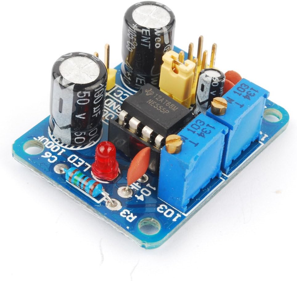
The module utilizes the NE555 timer IC as its main component, offering a wide frequency range from 1Hz to 200kHz. Its compact design and adjustable parameters make it a versatile tool for hobbyists and professionals.
2. Product Features
- Main Chip: NE555 timer IC.
- Input Voltage: 5V-15V DC.
- Output Current: Up to 15mA (at 5V input) or 35mA (at 12V input) when V-PP is greater than 50%.
- Output Amplitude: 4.2V V-PP to 11.4V V-PP (varies with input voltage).
- Frequency Range: Adjustable across four ranges:
- Low Frequency (LF): 1Hz ~ 50Hz
- Medium Frequency (MF): 50Hz ~ 1kHz
- High Frequency (HF): 1KHz ~ 10kHz
- Very High Frequency (VHF): 10kHz ~ 200kHz
- Duty Cycle: Adjustable.
- Visual Indication: Output with LED indication (LED ON for low level, LED OFF for high level; flashes at lower frequencies).
- Compact Size: Approximately 3.5cm x 3.6cm.
3. Setup Instructions
Follow these steps to set up your NE555 Signal Generator Module:
- Power Supply Connection: Connect a DC power source within the 5V to 15V range to the VCC and GND pins. Ensure correct polarity.
- Caution: Exceeding 15V DC may damage the module.
- Output Connection: Connect your target circuit or measurement device to the OUT pin. The signal ground should also be connected to the module's GND.
- Input Current: Ensure your power supply can provide at least 100mA of current.

4. Operating Instructions
The NE555 Signal Generator Module allows for adjustment of both frequency and duty cycle.
4.1. Frequency Adjustment
The module features a jumper to select the frequency range and two potentiometers (RA and RB) for fine-tuning the frequency within the selected range.
- Select Frequency Range: Use the jumper caps to select one of the four frequency ranges:
- Low Frequency (LF): 1Hz ~ 50Hz (C=0.001uF)
- Medium Frequency (MF): 50Hz ~ 1kHz (C=0.1uF)
- High Frequency (HF): 1KHz ~ 10kHz (C=1uF)
- Very High Frequency (VHF): 10kHz ~ 200kHz (C=100uF)
- Adjust Frequency: Rotate the potentiometers labeled RA and RB to adjust the output frequency. The frequency is determined by the formula:
T = 0.7 * (RA + 2 * RB) * C
Where T is the period (1/Frequency), RA and RB are the resistance values of the potentiometers (0-10K adjustable), and C is the capacitance value corresponding to the selected frequency gear.
4.2. Duty Cycle Adjustment
The duty cycle of the square wave output can also be adjusted using one of the potentiometers. Note that adjusting the duty cycle may slightly affect the overall frequency.
- Rotate the potentiometer (typically RB) to change the duty cycle.
- The output LED will indicate the state: ON for low level, OFF for high level. At lower frequencies, the LED will visibly flash, providing a visual representation of the output.
5. Specifications
| Parameter | Value |
|---|---|
| Main Chip | NE555 |
| Input Voltage | 5V - 15V DC |
| Input Current | ≥ 100mA |
| Output Amplitude (V-PP) | 4.2V (at 5V input) to 11.4V (at 12V input) |
| Max Output Current (5V input) | ≥ 15mA (V-PP > 50%) |
| Max Output Current (12V input) | ≥ 35mA (V-PP > 50%) |
| Frequency Range | 1Hz - 200kHz (adjustable via jumper selection) |
| Module Dimensions | 3.5cm x 3.6cm |
| Item Weight | 0.32 ounces |
| Package Dimensions | 3 x 1.9 x 1 inches |
| Model Number | EXPSFD006626 |

6. Maintenance
To ensure the longevity and proper functioning of your NE555 Signal Generator Module, observe the following maintenance guidelines:
- Storage: Store the module in a dry, dust-free environment away from direct sunlight and extreme temperatures.
- Cleaning: If necessary, gently clean the module with a soft, dry cloth. Avoid using liquids or abrasive cleaners.
- Handling: Handle the module by its edges to avoid touching the electronic components, which can be sensitive to static discharge.
- Power Off: Always disconnect the power supply before making any physical connections or disconnections to the module.
7. Troubleshooting
If you encounter issues with your NE555 Signal Generator Module, refer to the following troubleshooting tips:
- No Output Signal:
- Verify that the input voltage is within the 5V-15V DC range and correctly connected (VCC and GND).
- Check if the power supply can deliver at least 100mA.
- Ensure the output (OUT) pin is correctly connected to your measurement device or circuit.
- Confirm that the frequency range jumper is properly seated.
- Incorrect or Unstable Frequency:
- Ensure the potentiometers (RA and RB) are not at their extreme limits or faulty.
- Verify the correct frequency range is selected via the jumper.
- If the frequency becomes unstable or goes to DC at higher settings, the NE555 chip itself might be faulty and require replacement.
- Check for loose connections or solder joints on the module.
- LED Not Functioning:
- The LED indicates the output state (ON for low, OFF for high). At very high frequencies, it may appear continuously ON or OFF due to rapid switching.
- At very low frequencies, the LED should visibly flash. If it does not, check the output signal with an oscilloscope.
- Difficulty with Pin Connections:
- Refer to Figure 3.1 for a visual guide to the VCC, GND, and OUT pin locations.
- If a diagram was not included with your purchase, this manual serves as a reference.
8. Warranty and Support
Information regarding product warranty and customer support was not provided in the available product data. Please refer to your purchase documentation or contact the retailer directly for details on warranty coverage and technical assistance.