1. Product Overview
The Supco Camstat PR2412036W Pilot Re-Igniter Kit is designed to prevent pilot flames in furnaces from extinguishing. This kit includes a Camstat control module, an ignition cable, an ignitor electrode assembly, and necessary mounting hardware, providing a reliable solution for maintaining consistent pilot operation.
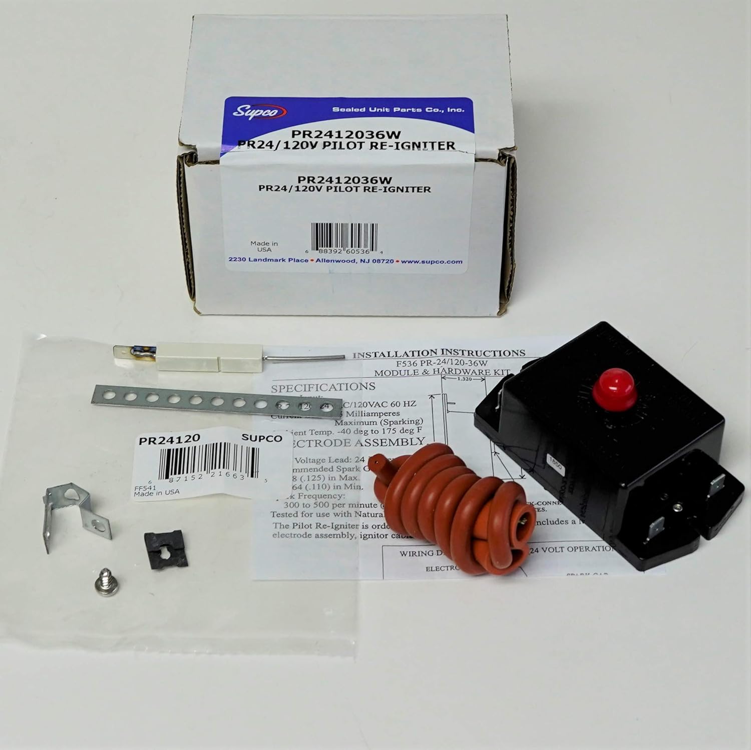
Image 1.1: Overview of the Supco Camstat PR2412036W Pilot Re-Igniter Kit, showing the product packaging, the Camstat control module, ignition cable, ignitor electrode, and mounting hardware.
2. Safety Information
Please read and understand all safety instructions before attempting installation or maintenance. Failure to follow these instructions could result in property damage, personal injury, or death.
- Always disconnect power to the furnace before installing or servicing any components.
- Installation should be performed by a qualified technician.
- Verify all electrical connections are secure and correct according to local codes and manufacturer specifications.
- Do not operate the furnace if any components are damaged or improperly installed.
3. Package Contents
The Supco Camstat PR2412036W kit typically includes the following components:
- Camstat Control Module (PR-24/120-00)
- Ignition Cable
- Ignitor Electrode Assembly
- Mounting Hardware (bracket, screw, clip)
- Installation Instructions

Image 3.1: The Camstat PR-24/120-00 control module, which is the primary component of the re-igniter kit. It features input terminals for 24VAC and 120VAC.

Image 3.2: The coiled red ignition cable, which connects the control module to the ignitor electrode assembly.
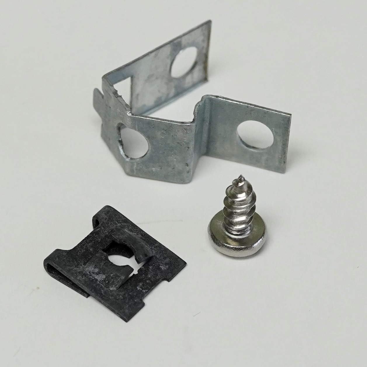
Image 3.3: The ignitor electrode assembly, typically made of ceramic and metal, responsible for generating the spark. Also shown is a perforated metal strap for mounting.

Image 3.4: Various mounting hardware components, including a metal bracket, a self-tapping screw, and a U-shaped clip, used to secure the igniter components within the furnace.
4. Setup and Installation
Installation of the Supco Camstat PR2412036W Pilot Re-Igniter Kit requires careful attention to electrical connections and furnace safety procedures. It is strongly recommended that installation be performed by a qualified HVAC technician.
General Steps:
- Power Disconnection: Turn off all electrical power to the furnace at the main breaker or fuse box.
- Access Pilot Assembly: Locate and access the furnace's pilot light assembly.
- Remove Old Igniter (if applicable): Carefully disconnect and remove the existing pilot igniter components.
- Mount New Components: Using the provided mounting hardware, securely install the new Camstat control module and ignitor electrode assembly in appropriate locations, ensuring proper clearance and alignment.
- Connect Wiring: Connect the ignition cable between the control module and the ignitor electrode. Follow the wiring diagram provided with the kit for electrical connections to the furnace's control system. The module supports 24VAC or 120VAC input.
- Verify Connections: Double-check all connections for security and correctness.
- Restore Power: Once installation is complete and verified, restore power to the furnace.
- Test Operation: Initiate a heating cycle to confirm proper pilot ignition and operation.
Refer to the detailed installation instructions included in your kit for specific wiring diagrams and mounting guidelines relevant to your furnace model.
5. Operating Instructions
The Supco Camstat Pilot Re-Igniter Kit operates automatically to maintain the pilot flame. Once installed and powered, the module monitors the pilot flame. If the pilot flame extinguishes, the re-igniter will automatically generate a spark to re-light it, ensuring continuous and safe furnace operation without manual intervention.
6. Maintenance
Regular maintenance of your furnace, including the pilot assembly, is crucial for optimal performance and safety. While the re-igniter kit itself requires minimal maintenance, consider the following:
- Annual Inspection: Have a qualified HVAC technician inspect your furnace annually. They can check the ignitor electrode for wear, carbon buildup, or damage.
- Cleanliness: Ensure the area around the pilot assembly and ignitor is free from dust, debris, and obstructions.
- Component Check: During inspections, verify that all wiring connections to the control module and ignitor are secure and free from corrosion.
7. Troubleshooting
If your furnace pilot is not lighting or staying lit, consider these troubleshooting steps:
- No Pilot Light:
- Check if the furnace has power.
- Ensure the gas supply to the furnace is open.
- Inspect the ignitor electrode for cracks, carbon buildup, or damage. A dirty or damaged electrode may not spark effectively.
- Verify all wiring connections to the control module and ignitor are tight and correct.
- Pilot Lights but Goes Out:
- The flame sensor (part of the ignitor assembly) might be dirty or faulty. Clean the flame sensor rod gently with fine sandpaper or steel wool.
- Ensure the pilot flame is strong and consistently engulfs the flame sensor. Adjust pilot gas pressure if necessary (this should be done by a qualified technician).
- Check for drafts that might be blowing out the pilot flame.
- No Spark from Ignitor:
- Confirm the control module is receiving the correct voltage (24VAC or 120VAC).
- Check the ignition cable for damage or loose connections.
- The control module itself may be faulty.
If these steps do not resolve the issue, contact a qualified HVAC technician for further diagnosis and repair.
8. Specifications
| Feature | Specification |
|---|---|
| Model Number | PR2412036W |
| Control Number | Camstat PR-24/120-00 |
| Input Voltage | 24VAC / 120VAC |
| Current Draw | 75 mA (MAX.) |
| Frequency | 50/60 Hz |
| Package Dimensions | 5.5 x 2.5 x 2.5 inches |
| Item Weight | 6.4 ounces |
| Manufacturer | SUPCO |
| Batteries Required | No |
9. Warranty and Support
For warranty information and technical support, please refer to the documentation included with your product or contact Supco directly. Warranty terms typically cover manufacturing defects for a specified period from the date of purchase.
For further assistance, you may visit the official Supco website or contact their customer service department.