
1. Introduction
This manual provides comprehensive instructions for the assembly, installation, and maintenance of your CiT F3 Micro-ATX PC Gaming Case. Please read this manual carefully before beginning installation to ensure proper setup and safe operation. This case is designed to support Micro-ATX and Mini-ITX motherboards.
2. Product Overview
The CiT F3 is a Micro-ATX tower case featuring a stylish design with a windowed side panel and mesh elements for enhanced airflow. It includes pre-installed LED fans and convenient front panel I/O ports.
Key Features:
- Motherboard Support: Micro-ATX, Mini-ITX
- Airflow: Mesh front and top panels for improved ventilation.
- Cooling: Supports up to four 120mm fans; two 120mm blue LED fans included.
- Storage: Multiple bays for 2.5" and 3.5" drives.
- Front I/O: 1 x USB 3.0, 2 x USB 2.0, HD Audio (Headphone & Microphone), SD/TF Card Reader.
- Aesthetics: Windowed side panel and black powder-coated interior.

Figure 2.1: Front and side view of the CiT F3 case, highlighting the mesh front, blue LED fans, and windowed side panel.

Figure 2.2: Top view of the CiT F3 case, illustrating the top mesh panel for airflow and the conveniently located front I/O ports.
3. Setup and Installation
3.1 Preparing the Case
- Unpack the case and remove all packaging materials.
- Place the case on a stable, flat surface.
- Remove the side panels by unscrewing the thumbscrews at the rear of the case and sliding the panels backward.
3.2 Motherboard Installation
The CiT F3 supports Micro-ATX and Mini-ITX motherboards.
- Install the I/O shield provided with your motherboard into the opening at the rear of the case.
- Align your motherboard with the pre-installed standoffs inside the case. Ensure all standoff holes on the motherboard match the standoffs.
- Secure the motherboard using the appropriate screws. Do not overtighten.

Figure 3.1: Internal view of the CiT F3 case, illustrating the motherboard tray and cutouts for cable management.
3.3 Power Supply Installation
The power supply unit (PSU) is mounted at the bottom of the case.
- Position the PSU in the dedicated compartment at the bottom rear of the case, ensuring the fan faces downwards for optimal cooling (if the case has a bottom vent).
- Secure the PSU to the rear of the case using screws.
3.4 Drive Installation
The case provides bays for both 2.5" SSDs and 3.5" HDDs.
- For 3.5" HDDs, slide the drive into the designated 3.5" drive cages and secure with screws or tool-less mechanisms if available.
- For 2.5" SSDs, mount them onto the dedicated 2.5" mounting points, typically located on the motherboard tray or drive cages, and secure with screws.

Figure 3.2: Internal view showing the flexible storage options for 2.5-inch and 3.5-inch drives within the case.
3.5 Fan Installation
The case supports up to four 120mm fans. Two 120mm blue LED fans are pre-installed.
- Identify available fan mounting points (front, rear, top).
- Mount additional 120mm fans using screws, ensuring correct airflow direction (intake or exhaust).
- Connect fan power cables to your motherboard or power supply.

Figure 3.3: Side view of the CiT F3 case, indicating the capacity for additional cooling fans and the transparent side panel.
3.6 Cable Management
Utilize the cutouts and space behind the motherboard tray to route cables for a clean build and improved airflow. Secure cables with zip ties or Velcro straps.
3.7 Connecting Front Panel Cables
Connect the front panel cables (USB 3.0, USB 2.0, HD Audio, Power Switch, Reset Switch, Power LED, HDD LED, Card Reader) to the corresponding headers on your motherboard. Refer to your motherboard manual for specific header locations.
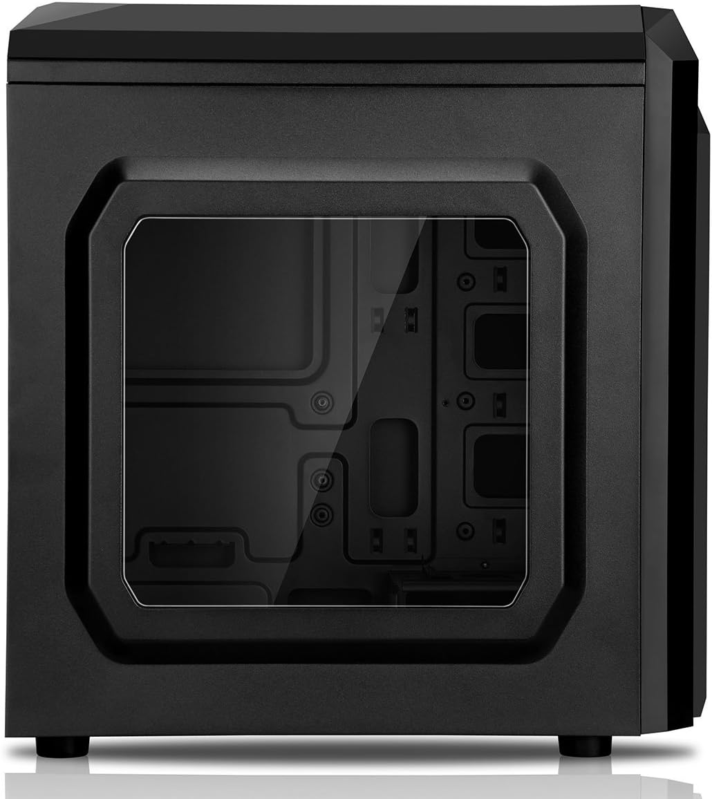
Figure 3.4: Rear view of the CiT F3 case, showing the I/O shield cutout, rear fan mount, and bottom-mounted power supply bay.
4. Operating Instructions
4.1 Powering On/Off
Press the power button located on the top panel to turn your system on or off. A short press typically powers on, while a longer press (usually 4-5 seconds) will force a shutdown.
4.2 Using Front I/O Ports
The top panel features convenient access to various ports:
- USB 3.0 Port (x1): For high-speed data transfer with compatible devices.
- USB 2.0 Ports (x2): For connecting standard USB devices.
- HD Audio Jacks: Separate ports for headphones (output) and microphone (input).
- SD/TF Card Reader: For direct access to data on SD and TF (MicroSD) memory cards.

Figure 4.1: Close-up view of the top-mounted front I/O panel, detailing the USB ports, audio jacks, and integrated card reader.
5. Maintenance
Regular maintenance helps ensure optimal performance and longevity of your PC components.
5.1 Dust Cleaning
- Periodically clean the mesh front and top panels to prevent dust buildup, which can restrict airflow. Use compressed air or a soft brush.
- Clean internal components (fans, heatsinks) with compressed air. Ensure the system is powered off and unplugged before cleaning.
5.2 Fan Inspection
Check fans regularly for dust accumulation or unusual noises. Clean or replace fans as necessary to maintain effective cooling.
6. Troubleshooting
This section addresses common issues you might encounter.
6.1 System Not Powering On
- Ensure the power cable is securely connected to both the PSU and the wall outlet.
- Verify the PSU switch is in the 'ON' position.
- Check all internal power connections (24-pin ATX, 8-pin CPU, GPU power) to the motherboard and components.
- Confirm front panel power switch cable is correctly connected to the motherboard header.
6.2 Fans Not Spinning / No LED Lights
- Check fan power connections to the motherboard or PSU.
- Ensure LED connections (if separate) are properly seated.
6.3 USB Ports / Card Reader Not Functioning
- Verify that the USB 3.0, USB 2.0, and card reader cables from the front panel are correctly connected to the corresponding headers on your motherboard.
7. Specifications
| Feature | Specification |
|---|---|
| Model Name | F3 |
| Case Type | Midi Tower (Micro-ATX) |
| Motherboard Compatibility | Micro ATX, ITX |
| Material | Alloy Steel |
| Color | Black/Blue Stripe (Blue variant) |
| Internal Bays Quantity | 4 (for 2.5" and 3.5" drives) |
| Hard Disk Form Factor | 3.5 Inches |
| Cooling Method | Air |
| Number of Fans Included | 2 x 120mm Blue LED Fans |
| Max Fan Support | Up to 4 x 120mm |
| Front I/O Ports | 1 x USB 3.0, 2 x USB 2.0, HD Audio, SD/TF Card Reader |
| Power Supply Mounting Type | Bottom Mount |
| Item Weight | 3.3 Kilograms |
8. Warranty and Support
For warranty information and technical support, please refer to the documentation provided with your purchase or visit the official CiT website. Warranty terms may vary by region and retailer.

