1. Introduction
This manual provides essential information for the safe and effective installation, operation, and maintenance of your TDPRO JCMOTO 24V 500W Brushed Speed Motor and Controller Set. This set is designed for various electric vehicles including scooters, go-karts, bicycles, e-bikes, tricycles, and mopeds. Please read this manual thoroughly before use to ensure proper function and longevity of the product.
2. Safety Information
Always prioritize safety when working with electrical components. Failure to follow these safety guidelines may result in injury or damage to the product.
- Ensure all power sources are disconnected before installation or maintenance.
- Wear appropriate personal protective equipment, including safety glasses and gloves.
- Verify correct voltage and current ratings for all connected components.
- Avoid short circuits by ensuring all connections are secure and insulated.
- Do not operate the motor or controller in wet conditions.
- Keep children and unauthorized personnel away from the work area.
3. Package Contents
Your package should contain the following items:
- 1x TDPRO JCMOTO 24V 500W Brushed Speed Motor
- 1x TDPRO JCMOTO 24V Controller
Inspect all components for any signs of damage upon receipt. If any items are missing or damaged, please contact your supplier immediately.
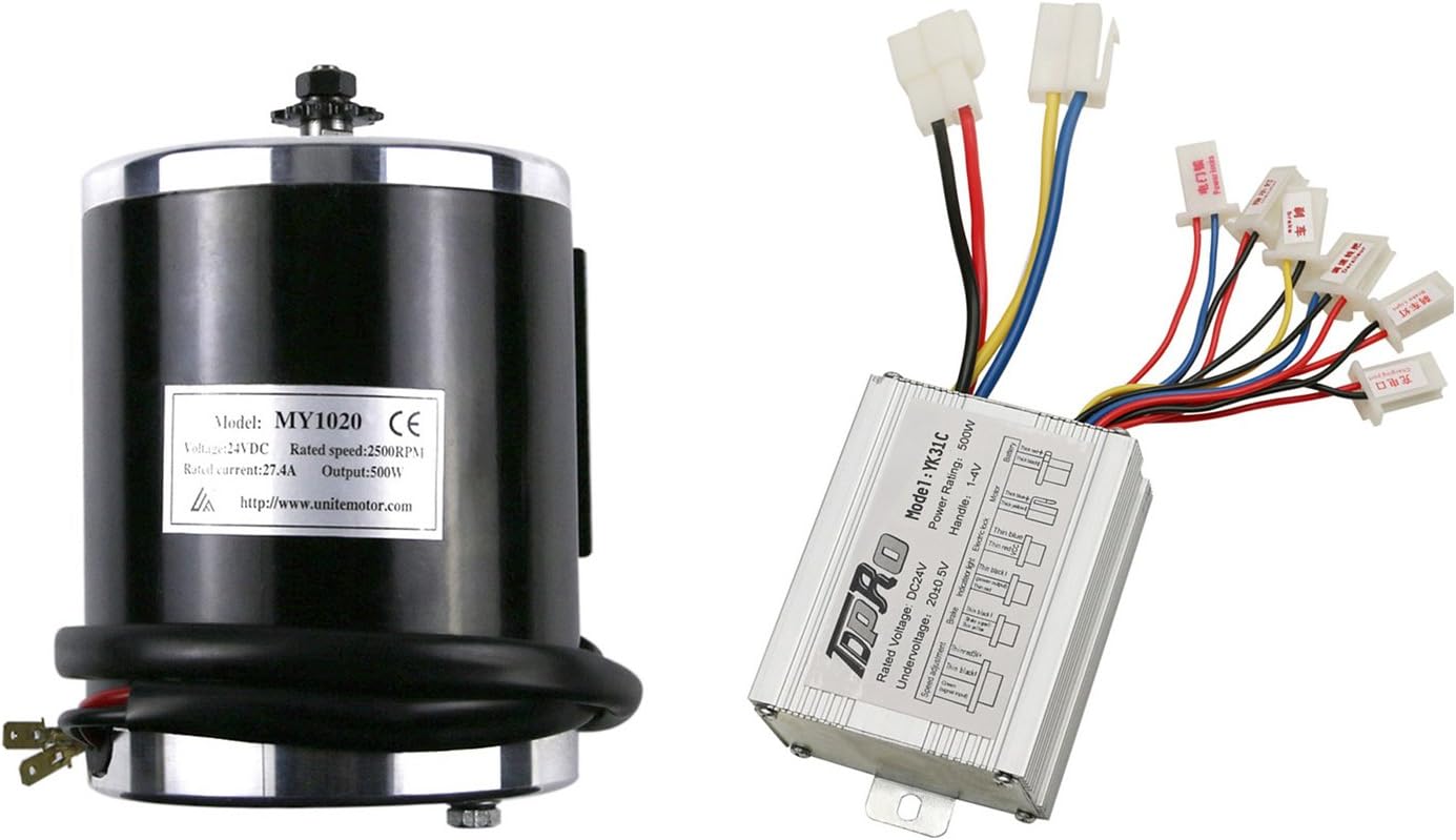
Figure 3.1: An overview of the TDPRO JCMOTO 24V 500W brushed electric motor and its accompanying controller, showcasing their general appearance.
4. Specifications
4.1 Motor Specifications
| Feature | Specification |
|---|---|
| Output | 500W |
| Rated Speed | 2400-2600 RPM (Nominal 2500 RPM) |
| Rated Voltage | 24V DC |
| Rated Current | 27.41A |
| No-load Current | ≤2.8A |
| Peak Efficiency (at 24V) | 80% |
| Reversible | Yes (with polarity swap) |
| Sprocket | 11 tooth for #25H chain |
| Horsepower | 0.68 HP |
| Material | Aluminum |
| Item Weight | 2500 Grams (approx. 5.5 lbs) |
| Model Number | TD01 |

Figure 4.1: Detailed specifications for the 24V 500W motor, including rated current, no-load current, rated torque, motor weight, rated rotating speed, and horsepower.

Figure 4.2: Technical drawing of the 24V 500W motor with key dimensions in millimeters, including overall height, width, and mounting hole spacing.

Figure 4.3: Top-down view of the 24V 500W motor, highlighting the 11-tooth sprocket for #25H chain.
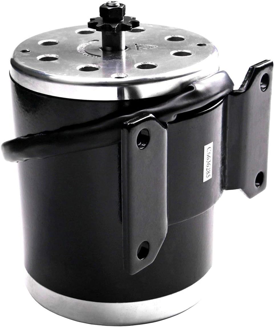
Figure 4.4: Side view of the 24V 500W motor, showing its robust construction and integrated mounting bracket.
4.2 Controller Specifications
| Feature | Specification |
|---|---|
| Rated Voltage | 24V DC |
| Conversion Efficiency | 95% |
| Under Voltage Protection | 20 ± 0.5V |
| Speed Regulator (Throttle) | 1-4 V |
| Model Number | TD03 (Model YK-31C) |
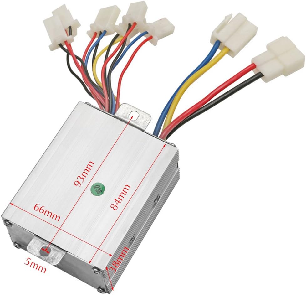
Figure 4.5: Technical drawing of the controller with key dimensions in millimeters, including length, width, and height.
5. Setup and Installation
This section outlines the general wiring procedure for the controller. Always refer to your specific vehicle's wiring diagram for detailed integration.
5.1 Controller Wiring Overview
The controller features 8 connectors. For basic operation, four groups of cables are essential: Battery, Motor, Ignition Lock, and Derailleur (throttle). Other connections are optional and can be integrated based on your application's requirements.
- Battery: Connect to your 24V DC battery pack.
- Motor: Connect to the 24V 500W motor.
- Brake: Connect to the brake lever switch.
- Brake Light: Connect to the brake light (if applicable).
- Indicator Light: Connect to the vehicle's indicator light (if applicable).
- Ignition Lock: Connect to the vehicle's ignition switch.
- Charger Port: Connect to the charging port for battery charging.
- Derailleur (Throttle): Connect to the speed regulator/throttle.
Ensure all connections are firm and correctly matched to prevent damage to the controller or motor.

Figure 5.1: A detailed view of the controller's wiring harness, showing labeled connectors for Battery, Motor, Power Lock, Derailleur (throttle), Charging Port, Braking, Indicator Light, and Brake Light.
6. Operation
Once the motor and controller are correctly installed and wired, follow these general steps for operation:
- Ensure the battery is fully charged.
- Turn the ignition lock to the 'ON' position.
- Gently apply the throttle to initiate motor movement. The speed regulator typically operates between 1-4V.
- Use the brake lever to slow down or stop the vehicle.
- Always operate the vehicle responsibly and within its design limits.
7. Maintenance
Regular maintenance ensures optimal performance and extends the lifespan of your motor and controller set.
- Cleaning: Keep the motor and controller free from dirt, dust, and moisture. Use a dry cloth for cleaning.
- Connections: Periodically check all electrical connections for tightness and corrosion. Secure any loose connections.
- Wiring: Inspect wiring for any signs of wear, fraying, or damage. Replace damaged wires immediately.
- Motor Bearings: The motor is a brushed type. While generally low maintenance, listen for unusual noises which may indicate bearing wear.
- Storage: When not in use for extended periods, store the components in a dry, cool environment.
8. Troubleshooting
This section provides basic troubleshooting steps for common issues. For complex problems, consult a qualified technician.
| Problem | Possible Cause | Solution |
|---|---|---|
| Motor does not run | No power to controller Loose wiring connections Faulty ignition lock Low battery voltage | Check battery connection and charge Inspect all wiring for secure connections Test ignition lock functionality Charge or replace battery |
| Motor runs intermittently | Loose wiring Faulty throttle Overheating | Check all connections Test throttle unit Allow motor/controller to cool down |
| Motor lacks power/speed | Low battery charge Incorrect gear ratio Motor overload | Charge battery fully Verify appropriate sprocket/chain setup Reduce load on the motor |
| Controller gets hot | Overload Short circuit Poor ventilation | Reduce load Check for short circuits in wiring Ensure adequate airflow around controller |
9. Warranty and Support
For warranty information and technical support, please refer to the documentation provided at the point of purchase or contact your retailer. Keep your purchase receipt as proof of purchase.
For general inquiries or further assistance, please contact TDPRO customer service through their official channels.