
Durablow TR1003
Durablow TR1003 Wireless Fireplace Remote Control Kit User Manual
Model: TR1003 | Brand: Durablow
1. Introduction
The Durablow TR1003 is a wireless remote control kit designed for gas heating appliances such as gas fireplaces. This kit includes a battery-powered RF transmitter with an LCD screen and a receiver, providing convenient control over your fireplace's ON/OFF functions, thermostat settings, and timer operations. It is compatible with millivolt valves and electric spark ignition modules (IPI modules).
2. Safety Information
- Important: This device is NOT a power supply or ignitor unit. It does not produce voltage itself but passes voltage from your fireplace's thermopile for safety reasons. If used as a switch, connect it in series with a power source or circuit.
- Professional Installation: Wiring instructions should only be performed by a qualified electrician or gas technician with knowledge of gas appliances and gas valves. Incorrect wiring can damage the gas valve, electronic module, and the remote receiver.
- Battery Safety: Use recommended batteries (e.g., Energizer Lithium Batteries). Any corrosion caused by battery leakage will be considered improper use.
3. Package Contents
Verify that all items listed below are included in your package:
- Remote Transmitter (with LCD screen)
- Receiver Box
- Wall Mount Cover Plate
- Screws
- Slide Switch
- Wires with Connectors (18-inch)
- Instruction Manuals
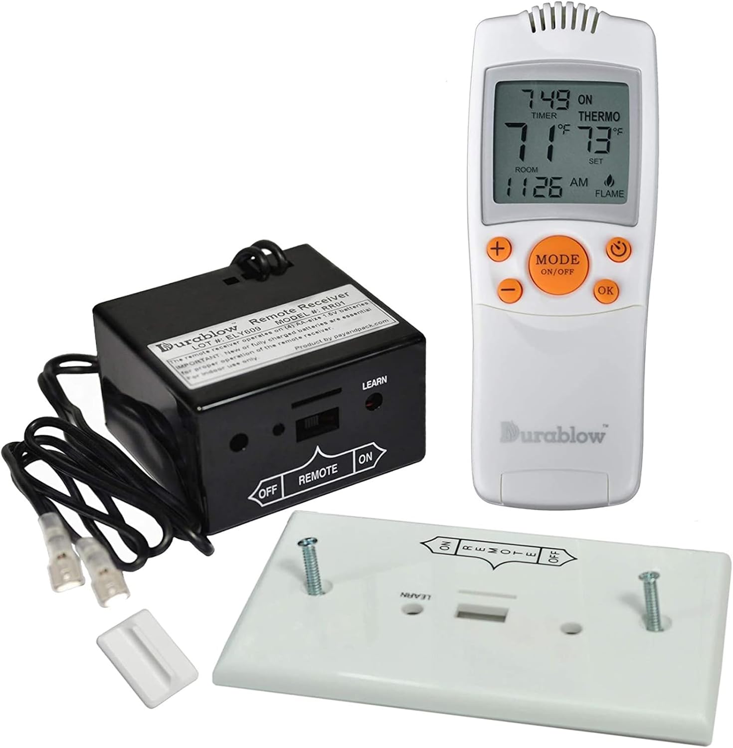
Image: Durablow TR1003 Remote Control Kit components, including the remote transmitter, receiver box, and wall plate.
4. Installation
4.1. Compatibility Check
Before installation, confirm your gas fireplace's compatibility. This remote control kit is designed for millivolt valves with TH and TH/TP terminals, or specific IPI (Intermittent Pilot Ignition) modules.
- Consult your fireplace's installation manual for the "Wiring Diagram" or check the rating plate inside/behind the fireplace to identify the gas valve type.
- Compatible IPI module models include: 593-592, GM-6KA, IPI-6000, SRV593-592, 350-M, IMP-1, J5760, J7728.

Image: Diagram illustrating a millivolt valve with TH and TP terminals for wiring connections.
4.2. Battery Installation
Install batteries in both the remote transmitter and the receiver box.
- Transmitter: Requires two (2) 1.5V AAA batteries.
- Receiver: Requires four (4) AA batteries.
- Ensure correct polarity. Batteries are not included. Energizer Lithium Batteries are recommended for optimal performance and to prevent leakage.
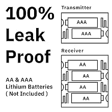
Image: Diagram illustrating the correct battery placement for both the remote transmitter (2 AAA) and the receiver unit (4 AA).
4.3. Wiring Instructions
Warning: Only qualified personnel should perform wiring. Incorrect wiring can cause damage.
4.3.1. Wiring to Millivolt Valve
Connect the receiver's 18-inch wires to the TH and TH/TP terminals on your gas millivolt valve. Ensure a secure connection.
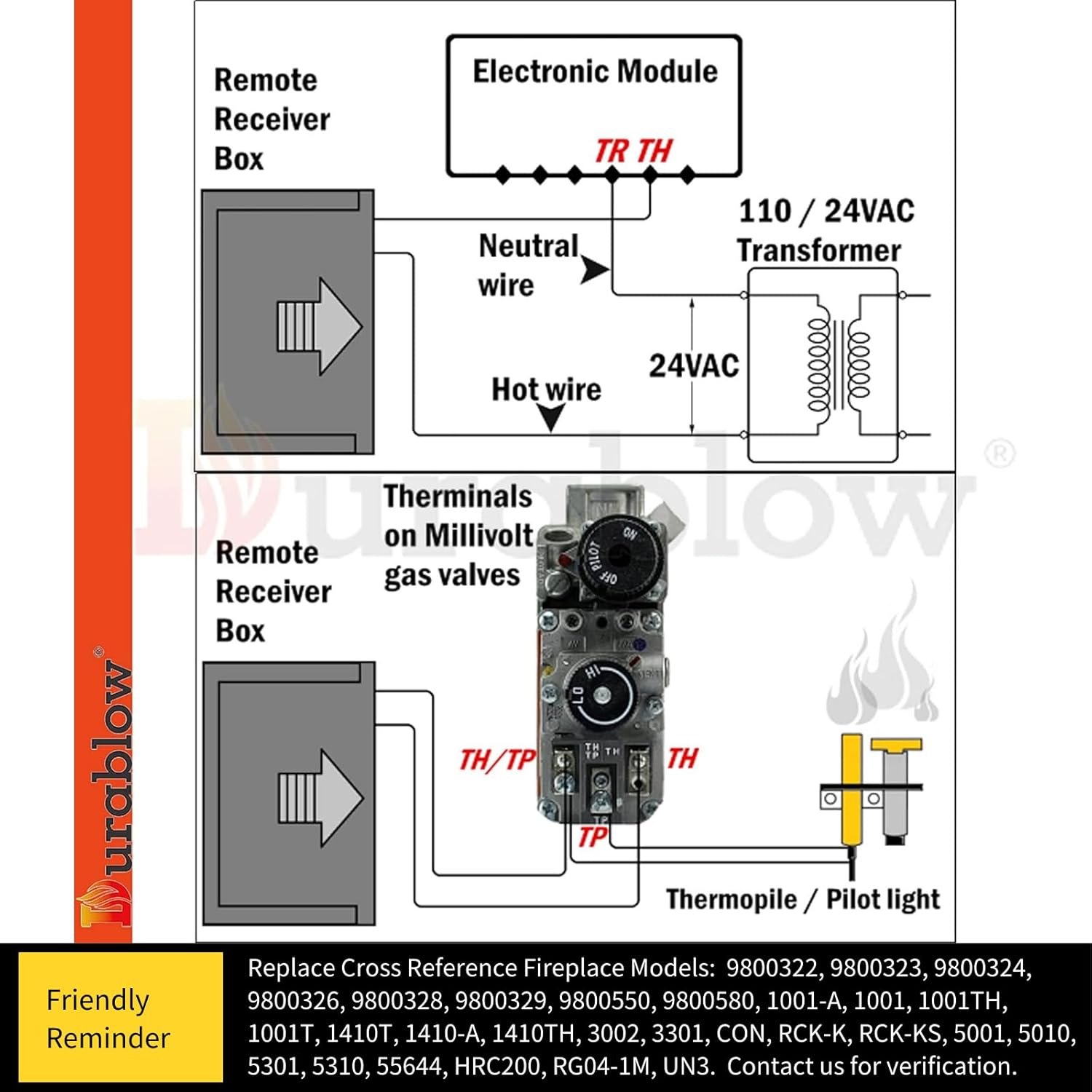
Image: Detailed wiring diagram showing how to connect the remote receiver box to a millivolt gas valve, indicating connections to TH and TH/TP terminals.
4.3.2. Wiring to IPI Pilot Ignition Control Module
For Dexen or S.I.T Electronic IPI Pilot Ignition Control Modules, locate the "OPTIONAL REMOTE CONTROL" wires on your module and connect the Durablow remote control kit wires to them.

Image: Wiring diagram illustrating the connection of the Durablow remote control to a fireplace using an SIT Control Module, highlighting the optional remote control connection points.

Image: Wiring diagram detailing the connection of the remote receiver to an IPI-6000 Ignition Module, showing correct and incorrect wall switch wiring scenarios.
The remote control can be wired in series or parallel depending on your existing setup. Refer to the diagrams below for guidance.

Image: Diagrams illustrating how to wire the remote control in series and in parallel with a millivolt valve.
4.4. Learning Function (Pairing)
The receiver features a "LEARN" function to pair with the transmitter. Consult the specific instructions included in your package for the pairing procedure. Typically, this involves pressing a button on the receiver and then a button on the transmitter within a short timeframe.

Image: Close-up view of the Durablow remote receiver box, highlighting the 'LEARN' button and the ON/OFF/REMOTE slide switch.
5. Operation
The remote transmitter allows control of your fireplace with various modes. The LCD screen displays current settings, room temperature, and set temperature.

Image: The Durablow remote transmitter, showing its LCD screen with current time, room temperature, and set temperature.

Image: Close-up view of the Durablow remote control buttons, labeled for Up (+), Down (-), Mode/On/Off, Timer, and OK/Set functions.
5.1. Basic ON/OFF Control
Press the MODE ON/OFF button to turn the fireplace ON or OFF. The receiver also has a slide switch with ON, REMOTE, and OFF positions. Set it to REMOTE for remote control operation.
5.2. Thermostat Mode
In thermostat mode, the fireplace will turn ON/OFF to maintain the set room temperature. The controllable temperature range is 45℉ (7℃) to 99℉ (37℃).
- Press the MODE ON/OFF button to cycle through modes until "THERMO" appears on the LCD.
- Use the + and - buttons to adjust the desired set temperature.
- The thermostat operates with room temperature swings of 1°F, 2°F, or 3°F. Refer to the detailed manual for changing the swing setting.
5.3. Timer Function
The timer feature allows you to set a duration for the fireplace operation, ranging from a 15-minute minimum to a 9-hour maximum.
- Press the TIMER button to activate and adjust the timer.
- Use the + and - buttons to set the desired duration.
- Press OK to confirm the timer setting.
5.4. Childproof Safety Lock
The remote transmitter includes a childproof safety lock feature. Consult your specific instruction manual for details on how to activate and deactivate this function.
6. Maintenance
6.1. Battery Replacement
Replace batteries in both the transmitter and receiver when the low battery indicator appears on the LCD screen or when the remote's range/responsiveness decreases. Always replace all batteries in a unit at the same time with new ones of the same type.
- Transmitter: Two (2) 1.5V AAA batteries.
- Receiver: Four (4) AA batteries.
Dispose of used batteries according to local regulations.
7. Troubleshooting
If your Durablow remote control is not functioning as expected, consider the following:
- No Ignition: Remember, the Durablow remote control is not an ignitor. Ensure your fireplace's ignition system is operational.
- No Response:
- Verify that the receiver and transmitter are within the operational range (up to 20 feet).
- Check if the receiver's slide switch is set to "REMOTE".
- Ensure batteries in both the transmitter and receiver are fresh and correctly installed.
- Re-pair the transmitter and receiver using the "LEARN" function if connection is lost.
- Millivolt Valve Issues: Check if the millivolt valve is in "IGNITE" mode.
- IPI Control Issues: Confirm that your IPI control module is working correctly.
For further technical assistance, refer to the FAQ section on the Durablow Brand Store or contact customer support.
8. Specifications
| Brand | Durablow |
| Model Number | TR1003 |
| Controller Type | Handheld Remote Control |
| Special Features | LCD Screen, Remote Control, Temperature Display, Thermostat Control, Timer |
| Color | White |
| Specific Uses | Gas Fireplace Remote Control |
| Temperature Control Type | Thermostatic |
| Connectivity Technology | RF (Radio Frequency) |
| Power Source | Battery Powered |
| Transmitter Batteries | 2 x 1.5V AAA (not included) |
| Receiver Batteries | 4 x AA (not included) |
| Display Type | LCD with Backlight |
| Mounting Type | Wall Mount (for receiver) |
| Operating Range | Up to 20 feet (non-directional RF signal) |
| Temperature Range | 45℉ (7℃) to 99℉ (37℃) |

Image: The receiver box with its dimensions clearly marked, showing length, width, and height.
9. Support and Warranty
Durablow products are designed with quality and reliability in mind, leveraging extensive industrial production experience. Components meet cUL, UL, CE, and FCC standards.
For technical questions, troubleshooting assistance, or further information, please visit the official Durablow Brand Store and refer to the FAQ section, or contact customer support directly.
Related documentsTR1003


Ask a question about this manual
Ask about setup, troubleshooting, compatibility, parts, safety, or missing instructions. Manuals+ will review the question and use this page’s manual context to help answer it.