1. Introduction
The WITMOTION WT901C-TTL is a high-performance 9-axis vibration inclinometer designed for precise angle, acceleration, and angular velocity measurements. It integrates a 3-axis gyroscope, a 3-axis accelerometer, and a 3-axis magnetometer, utilizing a Kalman filter for high-precision attitude determination. This module is suitable for applications such as four-axis flight control, self-balancing robots, and various angle and depth measuring systems.
Key Features:
- High Performance: Provides rock-solid data output including 3-axis XYZ (Pitch, Roll, Yaw) Acceleration, Gyro, Angle, Magnetic field, and Quaternion. Measurement range and output rate (0.2-200Hz) are selectable.
- Robust Design: Achieves 0.05° accuracy (Static) and 0.1° accuracy (Dynamic) for X and Y axes. Features a premium casing and small size for long-term measurement stability.
- Advanced Technology: Incorporates an 8-year professional attitude measuring solution provider's expertise, integrating R&D dynamic fusion algorithms and Kalman Filtering for stable data output, excellent bias stability, and low noise levels, enhancing measurement accuracy.
- Versatile Connectivity: Data output frequency up to 200Hz. Supports Serial port UART (TTL level) and I2C interfaces. Baud rate is configurable from 2400 to 921600 kps (default 9600kps).
- GPS Connectivity: Compatible with NMEA-0183 standard GPS data.
- Expansion Ports: Includes 4-way expansion ports for analog input and digital input/output.
2. Technical Specifications
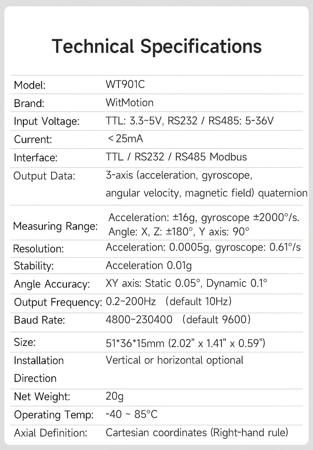
Figure 2.1: Detailed technical specifications for the WT901C-TTL Inclinometer, including model, brand, input voltage, current, interface, output data, measuring range, resolution, stability, angle accuracy, output frequency, baud rate, size, installation direction, net weight, operating temperature, and axial definition.
| Feature | Value |
|---|---|
| Brand | WITMOTION |
| Model | WT901C |
| Input Voltage | 3V-6V |
| Consumption Current | Typical 20mA |
| Dimensions (L x W x H) | 36mm x 51mm x 15mm |
| Measuring Axes | Attitude angle: 3 axis, Acceleration: 3 Axis, Angular Velocity: 3 Axis, Magnetic: 3 Axis |
| Acceleration Range | ± 16g |
| Angular Velocity Range | ± 2000 °/s |
| Attitude Measurement Precision | 0.05 degrees |
| Data Output Frequency | Up to 200Hz |
| Data Interface | Serial port UART (TTL level), I2C |
| Baud Rate | 2400-921600 kps (Default 9600kps) |
| GPS Connectivity | Accepts NMEA-0183 standard GPS data |
| Expansion Ports | 4-way for analog input and digital input/output |
3. Setup and Connection
The WT901C-TTL inclinometer can be connected to various devices, including microcontrollers like Arduino or a Windows PC, using a serial interface. Ensure you have the necessary USB-TTL cable and drivers.
3.1. Pin Definition

Figure 3.1: The WT901C-TTL inclinometer showing the VCC, RX, TX, and GND pins. VCC is for power, RX (Receive) connects to the host's TX, TX (Transmit) connects to the host's RX, and GND is for ground.
- VCC: Power supply (3V-6V)
- TX: Transmit data (connect to host's RX)
- RX: Receive data (connect to host's TX)
- GND: Ground
3.2. Connecting to a Microcontroller (e.g., Arduino)
Connect the WT901C-TTL sensor to your microcontroller using the TTL UART interface. Ensure correct pin connections:
- Sensor VCC to Microcontroller VCC (3V-6V)
- Sensor TX to Microcontroller RX
- Sensor RX to Microcontroller TX
- Sensor GND to Microcontroller GND
Refer to the microcontroller's documentation for specific UART pin assignments and power requirements.
3.3. Connecting to a Computer (Windows PC)
To connect the sensor to a Windows PC, you will need a USB-TTL serial converter. Follow these steps:
- Install Serial Driver: Install the appropriate serial driver (e.g., CH340 or CP2102) for your USB-TTL converter. These drivers are typically available on the manufacturer's website or included with the converter.
- Connect Hardware: Connect the WT901C-TTL sensor to the USB-TTL converter, ensuring VCC, TX, RX, and GND are correctly matched. Then, plug the USB-TTL converter into your PC.
- Verify COM Port: Open Device Manager on your PC and confirm that the USB-TTL converter is recognized and assigned a COM port number.
- Open Software: Launch the WitMotion PC software (Minimu.exe). The software should automatically detect the sensor and display data. If not, manually select the correct COM port and baud rate (default 9600) in the software settings.

Figure 3.2: Example of connecting the WT901C-TTL sensor to a device (smartphone in this case) using a USB-TTL adapter. The principle is similar for PC connection.
4. Operation and Data Display
Once connected, the WitMotion software (PC or mobile app) allows you to view real-time data from the inclinometer. The software typically displays acceleration, angular velocity, angle, and magnetic field data, often with graphical representations and 3D simulations.
4.1. Real-time Data Monitoring
The software interface provides various tabs or sections to monitor different sensor outputs:
- Acceleration: Displays acceleration values along X, Y, and Z axes.
- Angular Velocity: Shows angular velocity around X, Y, and Z axes.
- Angle: Presents pitch, roll, and yaw angles.
- Magnetic Field: Provides magnetic field strength readings.
- Raw Data: Displays the raw hexadecimal data received from the sensor.
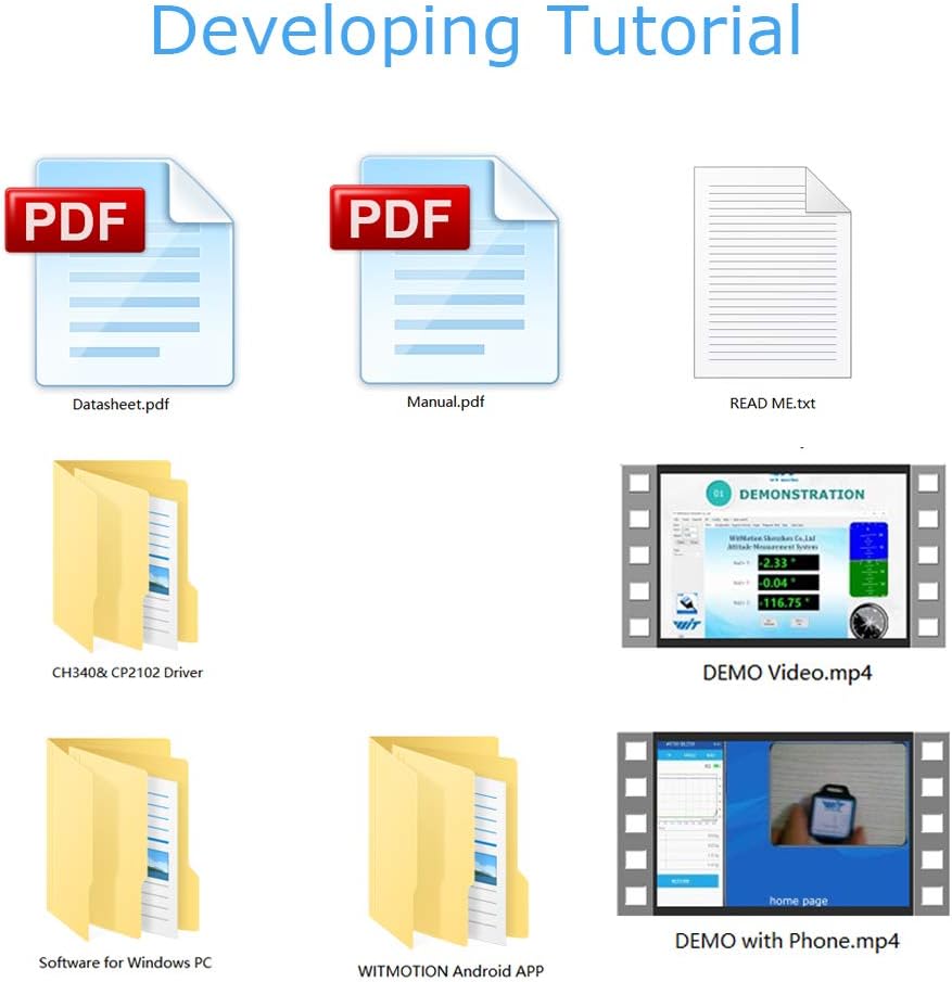
Figure 4.1: The WitMotion PC software displaying real-time sensor data, including acceleration, angular velocity, angle, and magnetic field, along with a 3D simulation of the sensor's orientation.
5. Calibration and Configuration
For optimal accuracy, it is essential to calibrate the inclinometer. The WitMotion software provides tools for acceleration and magnetic field calibration.
5.1. Acceleration Calibration
Acceleration calibration ensures accurate gravity vector measurement. Place the module on a horizontal surface before initiating calibration. The software will guide you through the process.
- In the software, navigate to the calibration section (e.g., "System" -> "Acceleration Calibration").
- Place the sensor module face up on a stable, horizontal surface.
- Click "Start Calibration" and wait for the system to automatically calculate calibration values. The process typically takes a few seconds.
- Once "Calibration is finished!" appears, the acceleration values should show approximately 0g for X and Y axes, and 1g for the Z axis (assuming the module is face up).
5.2. Magnetic Field Calibration
Magnetic field calibration compensates for local magnetic distortions, improving the accuracy of the digital compass. This process involves rotating the module in all directions.
- In the software, navigate to the calibration section (e.g., "System" -> "Magnetic Calibration").
- You will be prompted to rotate the module 360° around its X, Y, and Z axes respectively. Perform smooth, continuous rotations.
- The software will display a graph showing the magnetic field readings. The goal is to create a spherical distribution of points, which the software will use for ellipse fitting to determine offsets.
- After completing the rotations, click "End Calibration" and then "Write Parameter" to save the calibration data to the sensor.
Note: The accuracy of the Z-axis angle relies on magnetic field correction. Ensure the module is operated in an environment free from strong magnetic interference for best results.
6. Data Logging
Both the mobile app and PC software allow for data logging, enabling you to record sensor data over time for analysis.
- To start logging, click the "Record" button in the software interface.
- To stop logging, click "Stop".
- The recorded data is typically saved as a .txt file in a designated directory (e.g., on your phone's root directory or a specified folder on your PC).
- You can then open and analyze this .txt file using spreadsheet software or custom scripts.
7. Areas of Application
The WT901C-TTL inclinometer is a versatile sensor suitable for a wide range of applications requiring precise attitude and motion sensing:

Figure 7.1: Visual representation of various applications for the WT901C-TTL inclinometer, such as Virtual Reality (VR), robotics, industrial testing, and tilt angle monitoring in construction or machinery.
- Robotics: For balancing, navigation, and orientation control in robots.
- Drones/UAVs: Essential for flight stabilization and attitude control.
- Industrial Testing: Monitoring tilt and vibration in machinery and structures.
- Navigation Systems: Providing orientation data for various navigation platforms.
- Virtual Reality (VR) / Augmented Reality (AR): Head tracking and motion sensing.
- Human Motion Capture: Tracking body movements.
8. Troubleshooting
If you encounter issues with your WT901C-TTL inclinometer, consider the following common troubleshooting steps:
- No Data Output:
- Verify power supply to the module (3V-6V).
- Check all wiring connections (VCC, TX, RX, GND) for correctness and secure fit.
- Ensure the correct serial driver is installed for your USB-TTL converter.
- Confirm the correct COM port is selected in the software.
- Verify the baud rate setting in the software matches the sensor's default or configured baud rate (default 9600).
- Inaccurate Readings:
- Perform Acceleration Calibration as described in Section 5.1.
- Perform Magnetic Field Calibration as described in Section 5.2, ensuring a full 360° rotation around all axes.
- Ensure the sensor is not near strong magnetic fields or large metal objects that could interfere with the magnetometer.
- Check for physical vibrations or movements if static readings are expected.
- Software Connection Issues:
- Restart the WitMotion software and/or your computer.
- Try a different USB port or USB-TTL converter.
- Ensure no other applications are using the same COM port.
9. Warranty and Support
WITMOTION provides comprehensive support for its products:
- Warranty: 12-month warranty from the date of purchase.
- Customer Service: Lifetime friendly customer service from the WitMotion team.
- Tutorials and Documentation:
- A tutorial link is printed on the guiding card included in the product package.
- Complete tutorials and documentation are available on the official WitMotion wiki: https://wiki.wit-motion.com/english
- For further assistance, contact support at support@wit-motion.com.
- Development Resources: WitMotion provides PC software, smartphone apps, complete development materials, and SDKs to facilitate secondary development.

Figure 9.1: Overview of development and testing resources provided by WitMotion, including PC software, smartphone apps, SDKs, and various documentation formats like manuals and datasheets.