1. Introduction
This manual provides detailed instructions for the installation, operation, and maintenance of the DAE P203-200-S KIT Smart Submeter. This device is designed for accurate measurement of electrical energy consumption in 208/240V, 200A, 3P3W (3 hot wire, no neutral) systems. It is UL/cUL Listed and California CTEP approved, conforming to ANSI C12.1 and C12.20 national accuracy standards with a revenue-grade 0.5% accuracy.
The DAE P203-200-S KIT includes the submeter and two solid current transformers (CTs) with a 1.02" diameter, rated for 200A. This submeter is compatible with DAE Cloud Metering systems for remote data access and billing reports.
2. Safety Information
- Electrical Hazard: Installation and servicing of this equipment should only be performed by qualified and licensed electricians.
- Disconnect Power: Always ensure that power to the electrical panel is completely disconnected before attempting any installation, wiring, or maintenance.
- Proper Wiring: Follow all wiring diagrams and local electrical codes strictly. Incorrect wiring can lead to equipment damage, fire, or serious injury.
- Indoor Use: The meter is designed for indoor use. For outdoor applications, a suitable watertight enclosure (e.g., DAE B1725) is required.
- CT Orientation: Ensure current transformers (CTs) are installed with the correct orientation as indicated by arrows or markings.
3. Package Contents
The DAE P203-200-S KIT typically includes:
- DAE P203-200-S kWh Smart Submeter
- Two 200A Solid Current Transformers (CTs) with 1.02" diameter
- One in-line fuse with holder
- Lower cover with two 3/4" knockouts
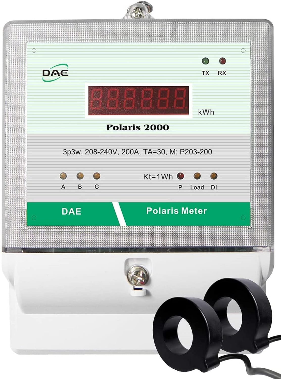
Figure 1: DAE P203-200-S KIT Smart Submeter with two solid current transformers.
4. Setup and Installation
The DAE P203-200-S meter is designed for 3-phase, 3-wire (3 hot wires, no neutral) systems. It requires voltage reference from three hot wires (A, B, C) and current measurement from two hot wires (A, C) using the provided CTs.
4.1. Wiring Connections
Refer to the wiring diagram below for proper connection. Ensure all connections are secure and comply with local electrical codes.
- Voltage Connections:
- Connect Hot Wire A to VA terminal of the Polaris meter. An in-line fuse with holder is attached for this connection.
- Connect Hot Wire B to VB terminal of the Polaris meter.
- Connect Hot Wire C to VC terminal of the Polaris meter.
- The meter is powered by VA and VN (internal). VB and VC only provide voltage reference and do not require in-line fuses.
- Current Transformer (CT) Connections:
- Connect the wires of the CTs from the electric panel to the green terminals of the Polaris meter.
- One CT measures current on Hot Wire A, and the other CT measures current on Hot Wire C.
- Ensure the CTs are installed with the correct direction of current flow, typically indicated by an arrow on the CT. The arrow should point towards the load.
- Connect the white or red wire of the CT to the CT+ terminal and the black wire to the CT- terminal.

Figure 2: Detailed 3P3W Wiring Diagram for DAE Polaris Meter. Connect Hot Wire A to VA, Hot Wire B to VB, Hot Wire C to VC. CTs connect to the green terminals for current measurement on Hot Wires A and C.
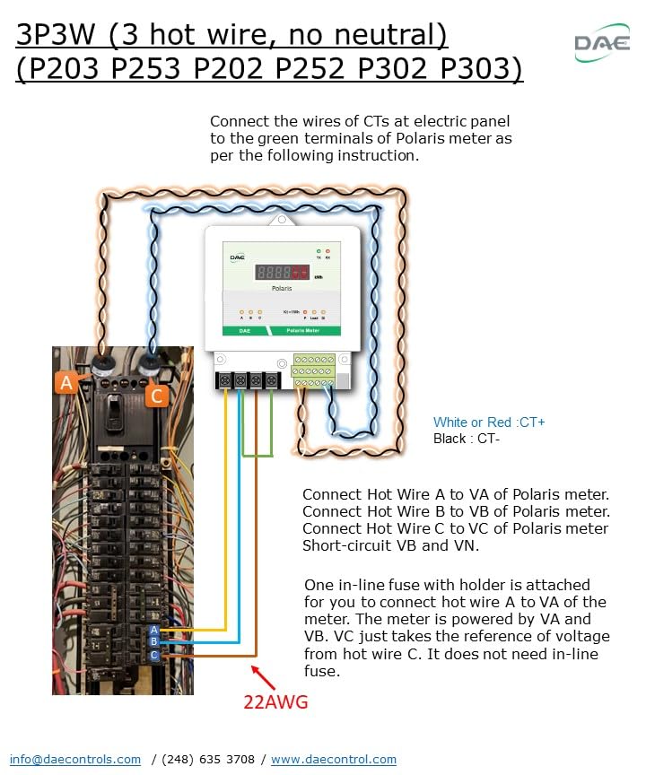
Figure 3: DAE Polaris Meter installed within a protective enclosure.
4.2. Conduits and Enclosure
The meter comes with a lower cover featuring two 3/4" knockouts for connecting conduits, ensuring a neat and protected installation.

Figure 4: Bottom view of the DAE Digital Energy Meter, showing the product label with model and electrical ratings.
5. Operating Instructions
Once properly installed and powered, the DAE P203-200-S submeter will begin measuring and displaying kWh consumption. The meter features TX (transmit) and RX (receive) indicators for communication status.
5.1. Cloud Metering Integration (Optional)
The P203-200-S KIT is compatible with DAE Cloud Metering systems, enabling remote monitoring and data management. This requires a DAE CC2030 Gateway (purchased separately).
- Standard Cloud System: The CC2030 Gateway collects energy data from DAE electrical meters via RS485 and sends it to a Cloud Server through an Ethernet connection to your router. Users can access real-time data, monthly kWh, and billing reports via PC, cell phone, or tablet. TOU (Time of Use) billing reports are also available. One CC2030 Gateway can support up to 20 meters.
- Wireless Cloud System: For installations where running an RS485 cable between the meter and the CC2030 Gateway is difficult, a wireless solution is available. This involves using two WSC500A RF Converters to establish a wireless connection between the meter and the CC2030 Gateway.

Figure 5: Cloud System Architecture for DAE kWh Meters. The meter connects to a CC2030 Gateway via RS485, which then connects to a router via Ethernet to send data to the DAE Cloud Server.

Figure 6: Wireless Cloud System Architecture for DAE kWh Meters. Polaris meters communicate wirelessly with the CC2030 Gateway via WSC500A RF Converters.
6. Maintenance
The DAE P203-200-S submeter is designed for long-term, reliable operation with minimal maintenance.
- Cleaning: Periodically clean the meter's exterior with a soft, dry cloth. Do not use abrasive cleaners or solvents.
- Inspections: Regularly inspect wiring connections for tightness and signs of wear or damage. Ensure the meter's enclosure remains sealed and free from moisture or debris.
- Calibration: The meter is factory calibrated to revenue-grade accuracy. Recalibration is generally not required under normal operating conditions. Factory Calibration Certificates are available upon request.
7. Troubleshooting
If the meter is not functioning as expected, consider the following common issues:
- No Display/Power:
- Check the main power supply to the electrical panel.
- Verify that Hot Wire A is correctly connected to the VA terminal and that the in-line fuse is intact.
- Ensure all voltage connections (VA, VB, VC) are secure.
- Incorrect Readings:
- Confirm that the CTs are installed with the correct orientation (arrow pointing towards the load).
- Check that the CT wires are securely connected to the green terminals (CT+ and CT-).
- Ensure the meter model matches the system voltage and amperage.
- Communication Issues (Cloud Metering):
- Verify RS485 wiring between the meter and the CC2030 Gateway.
- Check Ethernet connection between the CC2030 Gateway and the router.
- For wireless systems, ensure WSC500A RF Converters are properly installed and communicating.
- Consult the CC2030 Gateway manual for specific troubleshooting steps.
If issues persist after performing these checks, contact DAE Controls LLC technical support for assistance.
8. Specifications
| Feature | Specification |
|---|---|
| Model Number | P203-200-S KIT |
| Voltage Rating | 208/240V |
| Amperage Rating | 200A |
| Phase Configuration | 3P3W (3 hot wire, no Neutral) |
| Accuracy | 0.5% (Revenue-grade) |
| Certifications | UL/cUL Listed, California CTEP approved, ANSI C12.1, C12.20 |
| Current Transformers (CTs) | 2 x 200A Solid CTs (1.02" diameter) |
| Communication | RS485 (for Cloud Metering with CC2030 Gateway) |
| Dimensions | 7.42 x 5 x 2.24 inches |
| Weight | 3 Pounds |
Compatible CTs (available separately):
- Split Core CTs: DAE CT-5000SB (5000A), CT-3000SB (3000A), CT-2000SB (2000A), CT-1500SB (1500A), CT-1000SB (1000A), CT-600S (600A), CT-400S (400A), CT-200SB (200A), CT-100S (100A)
- Solid Core CTs: CT-600D9 (600A), CT-400D6 (400A), CT-200D3 (200A)
9. Warranty and Support
DAE Controls LLC is the manufacturer of this product. For warranty information, technical support, or to obtain Factory Calibration Certificates, please refer to the official DAE Controls website or contact their customer service.
A comprehensive User Guide (PDF) is available for download: DAE P203-200-S User Guide
For additional information and products, visit the DAE Store on Amazon.