1. Product Overview
The AKK X1 is a versatile 5.8GHz FPV (First Person View) video transmitter designed for remote-controlled aircraft and drones. It features switchable power output levels (25mW, 200mW, 600mW) to adapt to various flying environments and regulations. The integrated push button and digital display allow for easy configuration of channels, frequency bands, and power settings.
2. Key Features
- Switchable Power Output: Easily switch between 25mW, 200mW, and 600mW to optimize range and comply with local regulations.
- Wide Voltage Input: Supports a broad operating voltage range of 7-24V.
- 40 Channels: Covers A, B, E, F, and R bands, ensuring compatibility with most FPV receivers.
- Digital Display & Push Button: Intuitive interface for setting channels, bands, and power levels.
- Stable Performance: Designed for long transmission distance and reliable video signal.
- Video Format: Compatible with NTSC/PAL video formats.
- Antenna Connector: Utilizes an RP-SMA connector for secure antenna attachment.
3. Package Contents
Please verify that all items are present in your package:
- AKK X1 5.8G FPV Transmitter Module
- RP-SMA Antenna
- Wiring Harness (Power, Video, Audio)
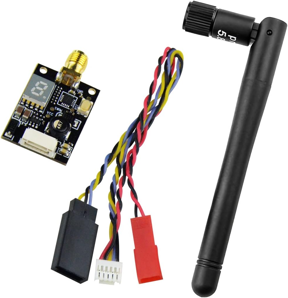
Figure 3.1: Contents of the AKK X1 package, showing the transmitter module, antenna, and connecting cables.
4. Product Diagram

Figure 4.1: AKK X1 FPV Transmitter module with labeled LED display and power switch, indicating button press durations for various settings.
5. Setup Instructions
5.1. Wiring Connections
Connect the AKK X1 transmitter to your flight controller or power distribution board (PDB) using the provided wiring harness. Ensure correct polarity and pin assignments to prevent damage.
- GND (Black): Ground connection.
- Audio (Yellow): Audio input from camera or flight controller (if applicable).
- Video (White): Video input from FPV camera.
- GND (Black): Additional ground connection.
- 7-24V (Red): Power input (7-24 Volts DC).

Figure 5.1: Detailed wiring diagram for the AKK X1, illustrating the correct pin connections for power, video, and audio.
5.2. Antenna Connection
Before powering on the transmitter, securely attach the RP-SMA antenna to the corresponding connector on the AKK X1 module. Operating the transmitter without an antenna can cause permanent damage.

Figure 5.2: RP-SMA antenna connection points, highlighting the male and female connector types for proper attachment to the VTX.
6. Operating Instructions
The AKK X1 features a single push button for all configuration settings. The digital LED display indicates the current channel, band, and power output.
6.1. Power On/Off
When the VTX is powered on, the blue LED display will show the current settings. If the display shows "0", the VTX is in an off or low-power state, typically indicating a pit mode or standby.
6.2. Channel Selection
To change the channel (CH), perform a short press (approximately 1 second) on the power switch button. The LED display will cycle through the available channels (1-8) within the current band.
6.3. Frequency Band Selection
To change the frequency band (FR), perform a medium press (approximately 2 seconds) on the power switch button. The LED display will cycle through the available bands (A, b, E, F, r).
6.4. Power Output Selection
To adjust the power output, perform a long press (approximately 5 seconds) on the power switch button. The LED display will flicker to indicate entry into power selection mode. After the flicker, subsequent short presses will cycle through the power levels:
- One hyphen (-) on LED: 25mW output.
- Two hyphens (--) on LED: 200mW output.
- Three hyphens (---) on LED: 600mW output.
7. Specifications
| Feature | Specification |
|---|---|
| Item Name | X1 5.8Ghz 40CH AV Transmitter |
| Modulation | Wideband FM |
| Video Format | NTSC/PAL |
| Output Impedance | 50 Ohm |
| Output Power | 25mW (12-14 dBm), 200mW (22-24 dBm), 600mW (26-28 dBm) |
| Antenna Connector | RP-SMA |
| Operating Voltage | 7-24 V |
| Supply Current (25mW) | 100 mA |
| Supply Current (200mW) | 200 mA |
| Supply Current (600mW) | 280 mA |
| Operating Temperature | -10 to +85 ℃ |
| Video Bandwidth | 0-18 MHz |
| Audio Carrier Frequency | 6.5 MHz |
| Video Input Level | 0.8, 1.0, 1.2 Vp-p |
| Video Input Impedance | 75 Ohm |
| Audio Input Level | 1.0 Vp-p |
| Audio Input Impedance | 10K Ohm |
| Dimensions (L x W x H) | 28.5 x 20 x 8 mm (1.1 x 0.8 x 0.3 inches) |
| Item Weight | 0.64 ounces |
8. Maintenance
Proper maintenance ensures the longevity and optimal performance of your AKK X1 FPV Transmitter:
- Secure Connections: Regularly check all wiring and antenna connections to ensure they are secure and free from damage. Loose connections can lead to signal loss or component failure.
- Heat Management: Ensure adequate airflow around the VTX, especially when operating at higher power outputs (200mW, 600mW). Excessive heat can degrade performance and shorten the lifespan of the module. Avoid enclosing the VTX in tight spaces without ventilation.
- Physical Protection: Protect the VTX from physical impacts, moisture, and dust. Consider using heat shrink tubing or a protective enclosure if exposed to harsh environments.
- Cleanliness: Keep the module clean and free from debris. Use a soft, dry brush or compressed air to remove dust.
9. Troubleshooting
If you encounter issues with your AKK X1 FPV Transmitter, refer to the following common problems and solutions:
- No Video Signal:
- Verify that the VTX is receiving power (7-24V) and the LED display is active.
- Ensure the antenna is securely connected to the RP-SMA port.
- Check that your FPV receiver is set to the correct channel and frequency band as the VTX.
- Confirm the video input wire from the camera is correctly connected to the VTX.
- Poor Video Quality / Interference:
- Ensure the VTX power output is appropriate for your environment (higher power for longer range, lower for close proximity to avoid interference with others).
- Check for nearby sources of electromagnetic interference (e.g., motors, ESCs, other electronic components).
- Inspect the antenna for damage or bends. A damaged antenna can severely degrade signal quality.
- Ensure your receiver antenna is also in good condition and correctly oriented.
- Verify that the video format (NTSC/PAL) matches your camera and receiver settings.
- VTX Overheating:
- Ensure the VTX has sufficient airflow, especially when operating at 600mW.
- Verify that the input voltage is within the specified 7-24V range. Overvoltage can cause excessive heat.
- Avoid running the VTX at high power for extended periods while stationary or without adequate cooling.
- VTX Not Powering On:
- Double-check all power wiring connections for correct polarity and secure contact.
- Measure the input voltage to ensure it is within the 7-24V operating range.
- Inspect for any visible damage to the VTX board or wiring harness.
10. Warranty and Support
For warranty information or technical support regarding your AKK X1 FPV Transmitter, please refer to the official AKK website or contact AKK customer service directly. Keep your purchase receipt as proof of purchase for any warranty claims.
AKK Official Website: www.akktek.com (Note: This is a placeholder URL, please refer to the actual manufacturer's website for support.)