Introduction
This manual provides detailed instructions for the installation, configuration, and maintenance of your Biostar TB85 Motherboard. The Biostar TB85 is designed to support Intel LGA 1150 processors and DDR3 memory, offering a stable and efficient platform for various computing needs. Please read this manual thoroughly before proceeding with installation to ensure proper setup and operation.
Setup
Proper installation is crucial for the stable operation of your motherboard. Follow these steps carefully.
1. Motherboard Layout
Familiarize yourself with the various components and connectors on the motherboard.

Figure 1: Biostar TB85 Motherboard Overview. This image displays the top-down view of the motherboard, highlighting the LGA 1150 CPU socket, four DDR3 RAM slots, multiple PCI Express slots, SATA ports, and various headers for front panel connections and USB ports.
2. CPU Installation (LGA 1150)
- Locate the LGA 1150 CPU socket on the motherboard.
- Gently push down the load lever and pull it to the side to open the CPU socket cover.
- Carefully align the CPU with the socket, ensuring the gold triangle on the CPU matches the triangle on the socket. Do not force the CPU into the socket.
- Lower the CPU into the socket.
- Close the socket cover and push the load lever back into its locked position.
- Apply thermal paste to the CPU and install the CPU cooler according to its manufacturer's instructions.
3. RAM Installation (DDR3)
- Locate the DDR3 memory slots. The Biostar TB85 has four DDR3 DIMM slots.
- Open the clips at both ends of the memory slot.
- Align the memory module with the slot, ensuring the notch on the module matches the key in the slot.
- Press down firmly on both ends of the memory module until the clips snap into place.
4. Motherboard Mounting
- Install standoffs in your PC case that align with the screw holes on the ATX motherboard.
- Carefully place the motherboard into the case, aligning the screw holes with the standoffs.
- Secure the motherboard with screws. Do not overtighten.
5. Power Supply Connections
- Connect the 24-pin ATX power connector from your power supply to the corresponding port on the motherboard.
- Connect the 8-pin (or 4-pin) ATX 12V CPU power connector to the port near the CPU socket.
6. Storage and Peripherals
- Connect SATA data cables from your storage devices (HDDs, SSDs) to the SATA 3 ports on the motherboard.
- Connect the front panel connectors (power button, reset button, HDD LED, power LED) to the appropriate headers on the motherboard. Refer to the motherboard diagram for exact pinouts.
- Connect USB 2.0 and USB 3.0 front panel headers if your case supports them.
- Install any PCI Express expansion cards (e.g., graphics card) into the available slots and secure them.
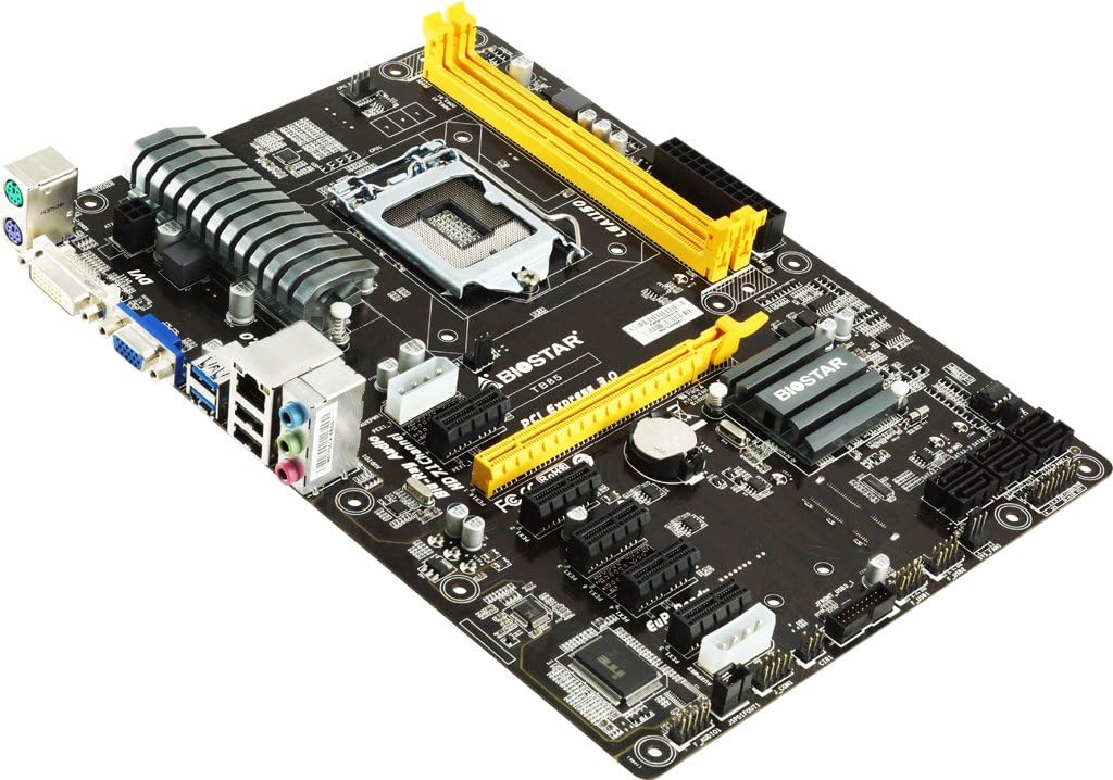
Figure 2: Biostar TB85 Motherboard Angled View. This image provides an angled perspective of the motherboard, showcasing the rear I/O panel with USB, audio, and video ports, as well as the CPU socket and the arrangement of PCI Express slots.
Operating
Once all components are installed, you can proceed with initial power-on and operating system setup.
1. First Boot
- Ensure all connections are secure.
- Connect your monitor, keyboard, and mouse.
- Power on your system. The system should perform a Power-On Self-Test (POST).
- If the system boots successfully, you will see the BIOS/UEFI splash screen or a prompt to enter setup.
2. BIOS/UEFI Setup
To access the BIOS/UEFI setup utility, press the DEL key during the POST process. In the BIOS/UEFI, you can configure various system settings, including boot order, CPU settings, memory timings, and peripheral options.
3. Operating System Installation
Insert your operating system installation media (USB drive or DVD) and set the boot order in the BIOS/UEFI to prioritize the installation media. Follow the on-screen prompts to install your preferred operating system (e.g., Windows 7, Windows 8).
Maintenance
Regular maintenance helps ensure the longevity and optimal performance of your motherboard.
1. Cleaning
- Periodically clean dust from the motherboard and components using compressed air. Ensure the system is powered off and unplugged before cleaning.
- Avoid using liquid cleaners directly on components.
2. BIOS Updates
Check the Biostar official website for the latest BIOS updates. BIOS updates can improve system stability, add support for new hardware, or fix known issues. Follow the update instructions provided by Biostar carefully to avoid damaging the motherboard.
3. Component Checks
Occasionally inspect cables and connections to ensure they are secure. Check for any signs of physical damage or overheating on components.
Troubleshooting
This section provides solutions to common issues you might encounter.
1. No Power / No Boot
- Verify that the power supply is connected correctly to the motherboard (24-pin ATX and 8-pin/4-pin CPU power).
- Ensure the power button cable from the case is correctly connected to the motherboard's front panel header.
- Test the power supply with another system or a power supply tester.
2. No Display Output
- Ensure the monitor is connected to the correct video output (either integrated graphics or a dedicated graphics card).
- Reseat the graphics card and memory modules.
- Try booting with only one RAM stick installed.
3. System Beep Codes
If your system emits a series of beeps during startup, these are POST (Power-On Self-Test) error codes. Consult the Biostar website or a general BIOS beep code reference for the specific meaning of the sequence. Common issues indicated by beep codes include memory errors, graphics card issues, or CPU problems.
4. Clearing CMOS
If you encounter boot issues or incorrect BIOS settings, you can clear the CMOS (Complementary Metal-Oxide-Semiconductor) to reset BIOS settings to default. To do this:
- Power off the system and unplug the power cord.
- Locate the CLR_CMOS jumper on the motherboard (refer to the motherboard diagram).
- Move the jumper from pins 1-2 to 2-3 for 5-10 seconds, then move it back to 1-2.
- Alternatively, remove the CMOS battery for 1-2 minutes and then reinsert it.
- Reconnect the power cord and power on the system.
Specifications
Key technical specifications for the Biostar TB85 Motherboard:
| Feature | Specification |
|---|---|
| Brand | Biostar |
| Model Number | TB85 |
| CPU Socket | LGA 1150 |
| Compatible Processors | Intel Core i7, i5, i3, Pentium (LGA 1150) |
| Chipset Type | Intel B85 |
| RAM Memory Technology | DDR3 |
| Memory Clock Speed | 1600 MHz / 1333 MHz / 1066 MHz |
| Memory Slots Available | 4 |
| Graphics Card Interface | PCI Express |
| System Bus Standard Supported | SATA 3 |
| Total USB Ports | 6 (including USB 2.0) |
| Platform | Windows 7, Windows 8 |
Warranty and Support
For warranty information and technical support, please refer to the official Biostar website or contact your local dealer. Keep your proof of purchase for warranty claims. The Biostar website typically provides drivers, BIOS updates, and additional support resources.
Official Biostar Website: www.biostar.com.tw


