HTI GSC60
HT Instruments GSC60 Power Analyzer and Electrical Safety Tester User Manual
Model: GSC60 | Brand: HTI
1. Introduction
This manual provides essential information for the safe and effective operation of the HT Instruments GSC60 Power Analyzer and Electrical Safety Tester. The GSC60 is a versatile instrument designed for comprehensive electrical safety tests and power quality analysis in accordance with VDE 0413 (EN61557) standards.
Please read this manual thoroughly before using the device to ensure proper understanding of its functions and safety precautions.

Figure 1.1: A user operating the GSC60 tester, demonstrating its handheld use and the clear display interface.
2. Safety Information
WARNING: Electrical testing can be hazardous. Always follow local safety regulations and use appropriate personal protective equipment (PPE).
- Ensure the instrument is in good working condition before each use.
- Do not use the device if it appears damaged or if any part of the insulation is compromised.
- Always disconnect power to the circuit before making connections, unless the test specifically requires live measurements and is performed by qualified personnel.
- Verify the correct voltage range and measurement function before connecting to a circuit.
- Avoid contact with live circuits.
- Refer to the specific test procedures for detailed safety guidelines for each measurement type.
3. Product Overview
The HT Instruments GSC60 is a robust, handheld device designed for a wide range of electrical measurements. It features a color display, intuitive navigation buttons, and various input terminals for probes and accessories.
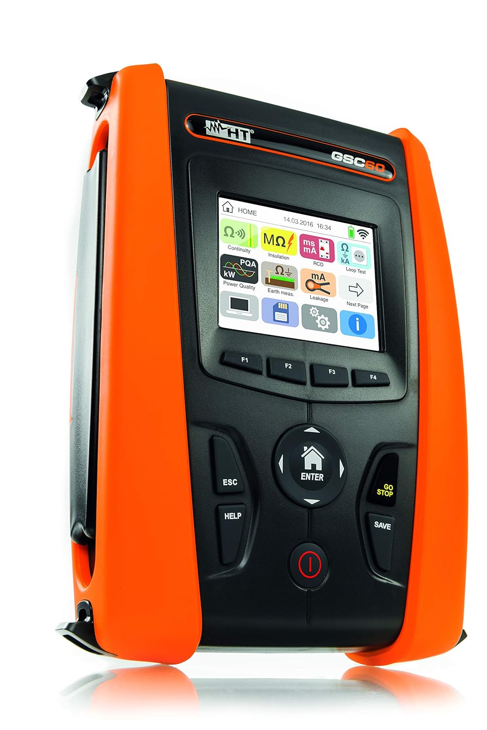
Figure 3.1: Front-side view of the GSC60 tester. This image shows the main unit with its orange protective casing, display screen, and control buttons.

Figure 3.2: Detailed front view of the GSC60, highlighting the color display and the arrangement of function keys (F1-F4), navigation buttons, and power/save controls.

Figure 3.3: The GSC60 home screen, displaying various measurement icons such as Continuity, Insulation, RCD Test, Power Quality Analysis, Earth Ground, and Leakage Current.
3.1 Key Components
- Display Screen: High-resolution color display for showing measurement results, settings, and graphical representations.
- Navigation Pad: Central directional buttons (Up, Down, Left, Right, ENTER) for menu navigation.
- Function Keys (F1-F4): Context-sensitive buttons located below the display.
- ESC Button: Returns to the previous screen or cancels an operation.
- HELP Button: Provides on-screen assistance for current functions.
- GO/STOP Button: Initiates or terminates a measurement.
- SAVE Button: Stores measurement data.
- Power Button: Turns the device on/off.
- Input Terminals: Various jacks for connecting test leads, current clamps, and other accessories.
4. Setup
4.1 Unpacking and Initial Inspection
Upon receiving your GSC60, carefully unpack all components and inspect for any signs of damage. The standard package includes the GSC60 unit, test leads, probes, and a carrying case.

Figure 4.1: The GSC60 tester and its accessories neatly organized within a protective hard case, including test leads, probes, and software CD.
4.2 Battery Installation and Charging
The GSC60 operates on 6 AA batteries (included). Ensure they are correctly installed according to the polarity markings in the battery compartment. For extended use or when batteries are low, connect the provided power adapter to the charging port.

Figure 4.2: A close-up view of the GSC60's charging port, showing a power adapter plug inserted, indicating the method for recharging the device.
4.3 Initial Power On and Language Selection
Press and hold the Power button to turn on the device. The first time you power on, you may be prompted to select a language and set the date/time. Follow the on-screen instructions using the navigation pad and ENTER button.
5. Operating Instructions
The GSC60 offers a variety of measurement functions accessible from the main menu. Select the desired test using the navigation buttons and press ENTER.

Figure 5.0: A test probe being connected to an electrical terminal within a control panel, illustrating a typical measurement setup.
5.1 Earth Conductor Continuity Test (VDE 0413 Part 4 / EN61557-4)
This test verifies the continuity of protective conductors with a test current greater than 200 mA.
- From the main menu, select the "Continuity" icon (often represented by Ω)).
- Connect the test leads to the protective conductor and the point to be tested.
- Press GO/STOP to initiate the measurement.
- The display will show the resistance value (R+, R-) and the test current.

Figure 5.1: The GSC60 display showing results for an Earth Conductor Continuity Test (RPE), indicating resistance values (R+, R-) and test currents, along with a pass/fail indicator.
5.2 Insulation Measurement (VDE 0413 Part 2 / EN61557-2)
Measures insulation resistance with selectable test voltages (50V, 100V, 250V, 500V, 1000V DC).
- Select the "Insulation" icon (MΩ) from the main menu.
- Choose the desired test voltage.
- Connect the test leads between the conductor and earth, or between two conductors.
- Press GO/STOP. Ensure the circuit is de-energized before testing.
5.3 RCD Test (VDE 0413 Part 6 / EN61557-6)
Tests Residual Current Devices (RCDs) of Type A, AC, B, B+, and F.
- Select the "RCD Test" icon from the main menu.
- Configure the RCD type, nominal current, and test mode (e.g., x1/2, x1, x5).
- Connect the test leads to the RCD protected circuit.
- Press GO/STOP. The device will measure tripping time and current.

Figure 5.2: The GSC60 display presenting RCD test results, including the measured tripping current in mA, voltage, and time, with a graphical pass/fail indication.

Figure 5.3: The RCD test settings screen on the GSC60, allowing selection of RCD type, test current (e.g., 10mA, 30mA), and test angle (0°/180°).
5.4 Line & Loop Impedance with IK Display (VDE 0413 Part 3 / EN61557-3)
Measures line and loop impedance, including prospective short-circuit current (IK). Also supports loop impedance measurement without RCD tripping.
- Select the appropriate impedance test from the main menu.
- Connect the test leads to the live circuit.
- Press GO/STOP.
5.5 Phase Sequence
Determines the correct phase sequence in three-phase systems.
- Select "Phase Sequence" from the main menu.
- Connect the three test leads to the phases.
- The display will indicate the phase rotation.
5.6 Earthing Measurement (VDE 0413 Part 5 / EN61557-5)
Supports 2-wire, 3-wire, and 4-wire methods for earth resistance measurement. Also includes earth measurement without auxiliary ground using the optional T2100 probe.
- Select "Earth Test" from the main menu.
- Choose the desired measurement method.
- Connect the necessary probes and auxiliary electrodes as per the selected method.
- Press GO/STOP.
5.7 Power Quality Analysis (PQA)
Records and analyzes power quality parameters, including real-time waveform display, harmonics, vector graphs, and voltage anomalies.
- Select "PQA" or "Netzanalyse" from the main menu.
- Connect current transformers (e.g., HT96U) and voltage leads to the system.
- Configure recording parameters (duration, interval).
- Press GO/STOP to begin recording.
- Review data on the device or export for further analysis.

Figure 5.4: The GSC60 display showing a real-time waveform for power quality analysis (PQA), illustrating voltage and current curves.

Figure 5.5: A screen from the GSC60 showing a summary of power quality analysis, including total energy (kWh), peak power (kW), and number of recordings.

Figure 5.6: The setup screen for Power Quality Analysis on the GSC60, illustrating connection diagrams and configurable parameters like voltage, current, and recording duration.

Figure 5.7: Multiple current clamps connected to electrical cables within a panel, demonstrating the setup for current measurement or power quality analysis.
5.8 Leakage Current Measurement
Measures leakage current starting from 1 mA with the optional clip-on ammeter HT96U.
- Connect the optional HT96U clip-on ammeter to the GSC60.
- Select "Leakage Current" from the main menu.
- Clamp the ammeter around the conductor to be measured.
- Press GO/STOP to read the leakage current.
5.9 Data Management and Storage
The GSC60 can record over 383 parameters for up to 2 months. Saved data can be organized and reviewed directly on the device or exported.

Figure 5.8: The GSC60's data management interface, displaying a hierarchical folder structure for organizing and accessing saved measurement data.
6. Maintenance
6.1 Cleaning
Clean the instrument and accessories with a soft, damp cloth. Do not use abrasive cleaners or solvents. Ensure the device is powered off and disconnected from any power source before cleaning.
6.2 Battery Replacement
When the battery indicator shows low power, replace the 6 AA batteries. Open the battery compartment, remove old batteries, and insert new ones, observing correct polarity. Dispose of old batteries according to local regulations.
6.3 Calibration
Regular calibration by authorized service centers is recommended to ensure the accuracy and reliability of the GSC60. Refer to the manufacturer's guidelines for recommended calibration intervals.
7. Troubleshooting
| Problem | Possible Cause | Solution |
|---|---|---|
| Device does not power on. | Low or depleted batteries; incorrectly installed batteries. | Replace batteries or connect to power adapter. Check battery polarity. |
| Inaccurate readings. | Incorrect test lead connection; uncalibrated device; environmental factors. | Verify connections. Consider professional calibration. Ensure stable testing environment. |
| RCD does not trip during test. | Incorrect RCD settings; faulty RCD; circuit issues. | Check RCD type and current settings. Inspect the RCD for faults. Consult a qualified electrician. |
| Display shows error message. | Measurement outside range; internal fault. | Refer to the specific error code in the full technical manual. If persistent, contact support. |
8. Specifications
- Model: GSC60
- Brand: HTI
- Electrical Safety Standards: VDE 0413 (EN61557) Part 2, 3, 4, 5, 6, 7
- Continuity Test Current: > 200 mA
- Insulation Test Voltages: 50V, 100V, 250V, 500V, 1000V DC
- RCD Types Supported: Type A, AC, B, B+, F
- Power Quality Analysis: Real-time waveform, harmonics, vector graphs, voltage anomalies (20ms resolution)
- Data Logging: Over 383 parameters, up to 2 months recording capacity
- Power Source: 6 AA batteries (included)
- Dimensions: Approximately 6.69 x 3.15 x 9.45 inches
- Weight: Approximately 10.36 Pounds
- Manufacturer: VISTA INSTRUMENTS
9. Warranty and Support
For warranty information, please refer to the documentation provided with your purchase or contact HT Instruments customer support. Keep your proof of purchase for warranty claims.
For technical assistance, troubleshooting beyond this manual, or service inquiries, please contact the manufacturer or your authorized distributor.