
1. Introduction
This manual provides essential information for the safe and effective operation of your CPS AC750 Multi-Functional AC/DC Clamp Meter. Please read this manual thoroughly before using the device to ensure proper function and to prevent potential hazards. Keep this manual for future reference.

Figure 1: CPS AC750 True-RMS Digital Clamp Meter. This image displays the clamp meter with its yellow and black casing, digital display, rotary dial, and test leads connected.
2. Safety Information
Always adhere to the following safety precautions to avoid personal injury or damage to the meter:
- Do not exceed the maximum input limits for any function.
- Use extreme caution when working with voltages above 60V DC or 30V AC RMS. These voltages pose a shock hazard.
- Before taking resistance or continuity measurements, disconnect power to the circuit and discharge all high-voltage capacitors.
- Ensure the meter is in good working condition. Do not use if damaged.
- Always use the correct function and range for measurements.
- Keep fingers behind the probe barriers when making measurements.
- The device is rated CAT III 1000V. Understand the implications of this rating for your application.
3. Product Features
The CPS AC750 is a versatile tool designed for electrical measurements. Key features include:
- Multi-Functional: Capable of measuring AC/DC current, AC/DC voltage, resistance, continuity, and more.
- Non-Contact Measurement: Allows for safe current measurement without direct contact with live conductors.
- Work Light: Integrated work light for improved visibility in dimly lit environments.
- CAT III 1000V Rating: Suitable for measurements in distribution boards, circuit breakers, wiring, including cables, bus-bars, junction boxes, switches, socket outlets in the fixed installation, and industrial equipment.
4. Setup
4.1 Unpacking and Inspection
Carefully unpack the clamp meter and its accessories. Inspect the device for any signs of damage. If any damage is found, do not use the meter and contact your supplier.
4.2 Battery Installation
The CPS AC750 is battery-powered. To install or replace batteries:
- Ensure the meter is turned off.
- Locate the battery compartment cover on the back of the meter.
- Use a screwdriver to open the battery compartment.
- Insert new batteries, observing correct polarity (+ and -).
- Replace the battery compartment cover and secure it with the screw.
4.3 Connecting Test Leads
For voltage, resistance, and continuity measurements, connect the test leads:
- Insert the red test lead into the "VΩmA" input jack.
- Insert the black test lead into the "COM" (common) input jack.
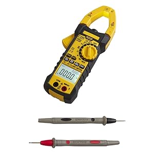
Figure 2: CPS AC750 Clamp Meter with test leads. This image shows the clamp meter and its red and black test leads, ready for connection.
5. Operating Instructions
5.1 Power On/Off
Rotate the central dial to the desired function to power on the meter. Rotate to "OFF" to power off.
5.2 AC/DC Current Measurement (Clamp Function)
- Rotate the dial to the AC A (Alternating Current Amperes) or DC A (Direct Current Amperes) position.
- Press the clamp trigger to open the jaws.
- Enclose a single conductor with the clamp jaws. Ensure the jaws are fully closed.
- Read the current value on the display.
- Note: For accurate readings, only one conductor should be within the clamp jaws.
5.3 AC/DC Voltage Measurement
- Connect the test leads as described in Section 4.3.
- Rotate the dial to the AC V (Alternating Current Volts) or DC V (Direct Current Volts) position.
- Touch the red probe to the positive side of the circuit and the black probe to the negative/ground side.
- Read the voltage value on the display.
5.4 Resistance Measurement
- Ensure the circuit is de-energized and all capacitors are discharged.
- Connect the test leads as described in Section 4.3.
- Rotate the dial to the Ω (Ohms) position.
- Touch the probes across the component or circuit section to be measured.
- Read the resistance value on the display.
5.5 Continuity Test
- Ensure the circuit is de-energized.
- Connect the test leads as described in Section 4.3.
- Rotate the dial to the continuity symbol (often shared with resistance).
- Touch the probes across the component or circuit section.
- A continuous beep indicates a complete circuit (low resistance).
5.6 Work Light Activation
The work light can be activated by pressing the dedicated button (refer to the meter's markings for the specific button). This feature is useful for illuminating the measurement area in low-light conditions.
6. Maintenance
6.1 Cleaning
Wipe the meter with a damp cloth and mild detergent. Do not use abrasives or solvents. Ensure the meter is completely dry before use.
6.2 Battery Replacement
Replace batteries when the low battery indicator appears on the display. Refer to Section 4.2 for battery installation instructions.
6.3 Storage
When not in use for extended periods, remove the batteries to prevent leakage. Store the meter in a cool, dry place, away from direct sunlight and extreme temperatures.
7. Troubleshooting
| Problem | Possible Cause | Solution |
|---|---|---|
| Meter does not power on. | Dead or incorrectly installed batteries. | Check battery polarity; replace batteries. |
| No reading or "OL" displayed. | Open circuit, out of range, or incorrect function selected. | Check connections; select appropriate range/function; ensure circuit is complete. |
| Inaccurate readings. | Low battery, interference, or incorrect measurement technique. | Replace batteries; move away from strong electromagnetic fields; review operating instructions. |
| Clamp jaws not closing properly. | Obstruction or damage. | Inspect jaws for debris; do not force closure. If damaged, discontinue use. |
8. Specifications
- Model: AC750
- Measurement Type: Multi-Functional AC/DC Clamp Meter (Ammeter, Voltmeter, Ohmmeter, Continuity)
- Safety Rating: CAT III 1000V
- Power Source: Battery Powered
- Style: Digital
- Item Weight: Approximately 1.6 Pounds (0.73 kg)
- Package Dimensions: Approximately 12.5 x 6.75 x 4 inches (31.75 x 17.15 x 10.16 cm)
- Special Features: Non-Contact Measurement, Work Light
9. Warranty and Support
For warranty information, technical support, or service inquiries, please refer to the official CPS Products website or contact their customer service department. Details regarding specific warranty periods and coverage are typically provided with the product packaging or on the manufacturer's official channels.
Note: Protection plans may be available for purchase separately. Refer to your retailer for details on extended protection options.