Introduction
This manual provides detailed instructions for the installation, operation, and maintenance of the Watt Stopper LMIO-301 Digital Lighting Management (DLM) Photocell Input Control Module. The LMIO-301 is designed to integrate photocell inputs into a DLM system, enabling automated lighting control based on ambient light levels. It features a 24VDC power requirement and an RJ45 connection for seamless integration.
Important Safety Information
Read all instructions before installing or using this product. Failure to follow these instructions may result in electrical shock, fire, or other hazards. This device is intended for indoor use only. Installation should be performed by a qualified electrician in accordance with all national and local electrical codes.
- Disconnect power at the circuit breaker or fuse before installing or servicing.
- Do not use this device with dimmers or other control devices not specified by the manufacturer.
- Ensure all connections are secure and properly insulated.
- Verify the power supply voltage matches the device's requirements (24VDC).
Setup and Installation
The LMIO-301 module is designed for easy integration into a Digital Lighting Management (DLM) system. Follow these steps for proper installation:
1. Mounting the Module
The module can be mounted in a suitable enclosure or junction box. Ensure adequate ventilation and access for wiring. The compact dimensions of 4 x 3 x 2 inches (approximately) allow for flexible placement.
2. Electrical Connections
The LMIO-301 requires a 24VDC power supply. Connect the module to the DLM network using an RJ45 cable. The module also provides a terminal block for connecting external photocells, such as LMPO or LMPS models.
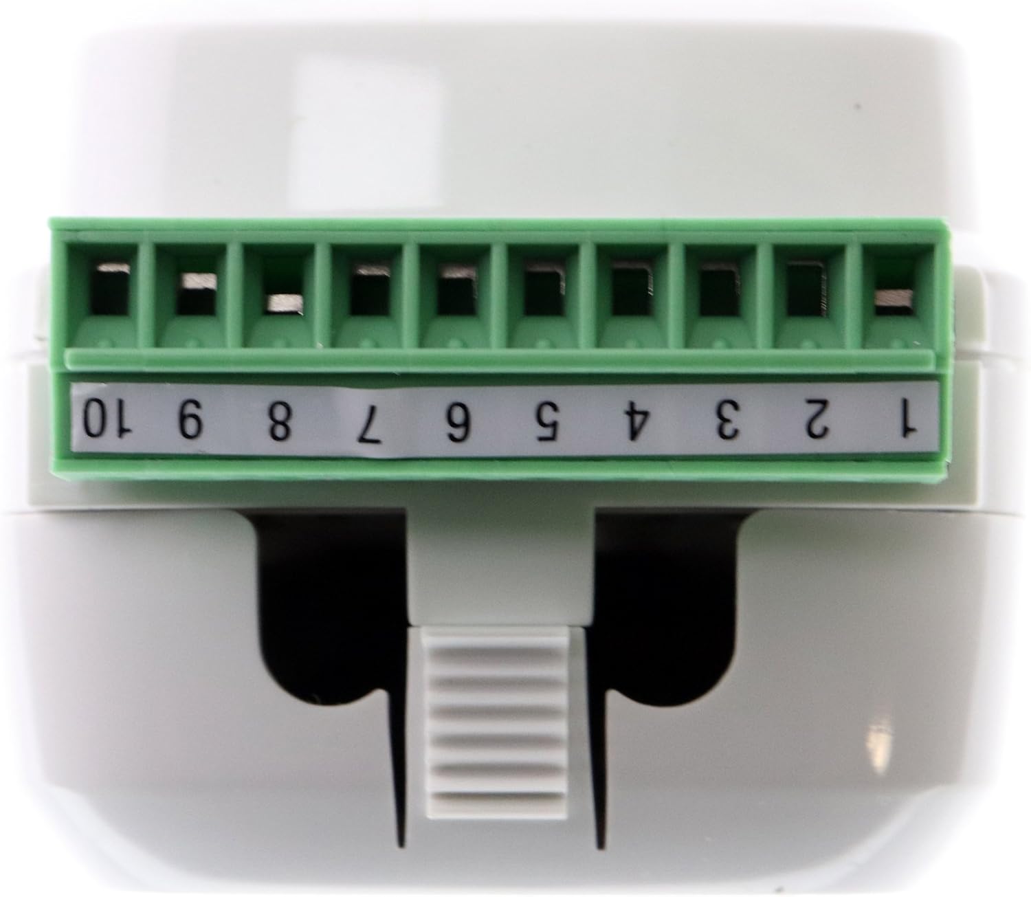
Figure 1: Top view of the LMIO-301 module showing the 10-position terminal block. This block is used for connecting external photocells and other low-voltage inputs. Ensure proper wiring according to the system design.
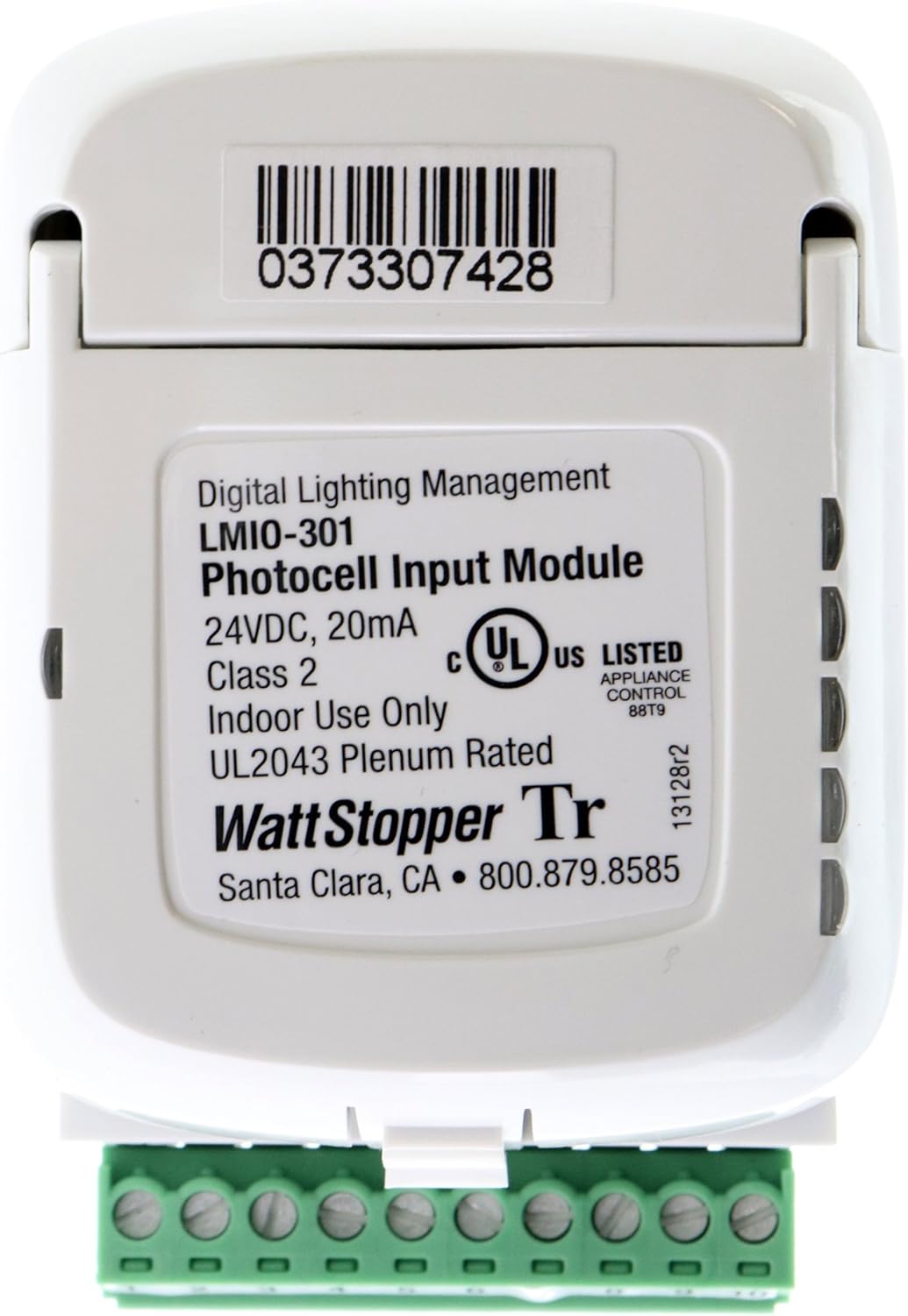
Figure 2: Rear view of the LMIO-301 module displaying the product label. This label includes critical information such as the model number (LMIO-301), voltage (24VDC, 20mA), UL listing, and manufacturer details. The barcode 0373307428 is also visible.
3. Terminal Block Wiring
The 10-position terminal block (visible in Figure 1) is used for connecting photocell sensors. Refer to the specific wiring diagrams provided with your photocell sensor (e.g., LMPO/LMPS) and the overall DLM system documentation for correct terminal assignments. Typically, these connections involve power, ground, and signal lines from the photocell.
- RJ45 Connection: Connect a standard RJ45 cable from the LMIO-301 to the DLM network. This provides both communication and 24VDC power to the module.
- Photocell Connections: Wire the photocell to the terminal block according to the photocell's installation guide. Ensure polarity is correct for power and signal lines.
Operating Instructions
The LMIO-301 functions as an input interface for photocells within a Digital Lighting Management (DLM) system. Once properly installed and connected, the module will automatically begin to receive data from the connected photocell(s).
- Automatic Light Level Detection: The connected photocell continuously monitors ambient light levels.
- Data Transmission: The LMIO-301 converts the analog signal from the photocell into digital data and transmits it over the DLM network via the RJ45 connection.
- System Integration: Other DLM devices (e.g., room controllers, dimming modules) receive this light level data and adjust connected lighting fixtures according to programmed settings. This enables daylight harvesting strategies, where artificial lighting is reduced or turned off when sufficient natural light is available.
- Configuration: Specific light level thresholds and control strategies are typically configured through the DLM system's software or commissioning tools, not directly on the LMIO-301 module itself.
Maintenance
The Watt Stopper LMIO-301 module is designed for reliable, long-term operation with minimal maintenance. However, periodic checks can help ensure optimal performance.
- Cleaning: If the module is exposed to dust or debris, gently wipe the exterior with a dry, soft cloth. Do not use liquid cleaners or solvents.
- Connection Inspection: Periodically inspect the RJ45 and terminal block connections to ensure they are secure and free from corrosion or damage.
- Photocell Sensor Maintenance: Ensure the connected photocell sensor lens is clean and unobstructed for accurate light level readings. Refer to the photocell's specific maintenance instructions.
- System Checks: Regularly verify the overall DLM system operation to confirm that lighting control based on photocell input is functioning as intended.
Troubleshooting
If the LMIO-301 module or the associated lighting control system is not functioning as expected, consider the following troubleshooting steps:
- No Power/Module Inactive:
- Verify that the 24VDC power supply to the DLM network is active.
- Check the RJ45 cable connection between the LMIO-301 and the DLM network for proper seating and damage.
- Ensure the circuit breaker supplying power to the DLM system is ON.
- Incorrect Light Level Readings/No Control:
- Inspect the wiring between the photocell and the LMIO-301 terminal block. Ensure all connections are secure and correctly wired according to the photocell's instructions.
- Check the photocell sensor itself for obstructions, dirt, or damage. Clean the lens if necessary.
- Verify that the photocell is compatible with the LMIO-301 and the DLM system.
- Consult the DLM system's commissioning software to ensure the photocell input is properly configured and assigned to the correct control zones.
- Communication Issues:
- Ensure the RJ45 cable is not damaged and is securely connected at both ends.
- Check other devices on the DLM network to see if they are communicating properly.
- If multiple DLM devices are experiencing communication issues, there may be a problem with the DLM network backbone or power supply.
If problems persist after performing these checks, contact Watt Stopper technical support for further assistance.
Specifications
| Feature | Detail |
|---|---|
| Manufacturer | Wattstopper |
| Part Number | LMIO-301 |
| Item Model Number | LMIO-301 |
| Product Dimensions | 4 x 3 x 2 inches |
| Item Weight | 1 pound |
| Color | White |
| Style | LMIO-301 |
| Finish | White |
| Material | LMIO-301 (Note: This typically refers to the product model, not the physical material. Consult manufacturer for material details.) |
| Power Source | Wired Electric |
| Voltage | 24 Volts DC |
| Wattage | 1111111 watts (Note: This value appears to be an error in the source data and should be disregarded for typical power consumption of such a module. Refer to manufacturer's official documentation for accurate wattage.) |
| Item Package Quantity | 1 |
| Number Of Pieces | 1 |
| Batteries Included? | No |
| Batteries Required? | No |
| ASIN | B01J9JF64C |
| Date First Available | June 21, 2017 |
Warranty Information
Specific warranty terms and conditions for the Watt Stopper LMIO-301 module are provided by the manufacturer at the time of purchase. Please refer to the documentation included with your product or contact Watt Stopper directly for detailed warranty information. Keep your proof of purchase for warranty claims.
Support and Contact Information
For technical assistance, product inquiries, or support, please contact Watt Stopper directly:
- Manufacturer: Watt Stopper
- Location: Santa Clara, CA
- Phone: 800.879.8585
- Product Barcode (UPC): 0373307428
- Online Resources: Visit the official Watt Stopper website for additional documentation, FAQs, and support resources.


