1. Introduction
This user manual provides essential information for the safe and effective operation of your Baomain 660V 40A 4 Positions 12 Terminals Changeover Control Rotary Cam Switch, model SZW26-40/0-3.3. Please read this manual thoroughly before installation and use to ensure proper function and to prevent damage or injury.

Figure 1: Baomain Rotary Cam Switch, front view. This image shows the main product with its black rotary handle and a silver faceplate indicating positions 0, 1, 2, and 3.
2. Product Overview
The Baomain Rotary Cam Switch is a robust electrical component designed for reliable circuit control. Key features include:
- Model: SZW26-40/0-3.3
- External Material: Durable Plastic casing
- Rated Insulation Voltage (Ui): 660V
- Rated Thermal Current (Ith): 40A
- Positions: 4 Positions (0-1-2-3)
- Terminals: 12 terminals for versatile wiring configurations
- Mounting: Suitable for mounting boards with thickness between 1mm to 4mm

Figure 2: Baomain Rotary Cam Switch with included mounting screws. This image displays the switch from an angled perspective, showing the front face and part of the blue body, alongside four mounting screws.
3. Specifications
Detailed technical specifications for the SZW26-40/0-3.3 switch:
| Specification | Value |
|---|---|
| Model | SZW26-40/0-3.3 |
| Rated Insulation Voltage (Ui) | 660V |
| Rated Thermal Current (Ith) | 40 Amps |
| Operation Mode | ON-OFF-OFF-OFF (Rotary) |
| Contact Type | No Nc |
| Circuit Type | 4-way |
| Terminal Type | Screw |
| Product Dimensions (L x W x H) | 2.55 x 2.55 x 4.25 inches (65 x 65 x 108mm) |
| Net Weight | 248g (approx. 1 Pound) |

Figure 3: Dimensional drawing of the Baomain Rotary Cam Switch. This image provides precise measurements of the switch, including its length, width, and height, in both inches and millimeters.
4. Setup and Installation
Safety First: Before beginning any installation, ensure that the power supply to the circuit is completely disconnected and locked out. Only qualified personnel should perform electrical installations.
4.1 Mounting
- Select a suitable mounting location on a panel or enclosure. The switch is designed for mounting boards with a thickness between 1mm and 4mm.
- Refer to Figure 3 for precise dimensions to cut the necessary opening and drill mounting holes.
- Insert the switch into the prepared opening and secure it using the provided screws.
4.2 Wiring
The switch features 12 screw terminals. Understanding the terminal numbering and the contact diagram is crucial for correct wiring.

Figure 4: Close-up view of the Baomain Rotary Cam Switch terminals with numbering. This image highlights the 12 screw terminals on the blue body of the switch, with numbers 1-12 clearly visible next to each terminal.
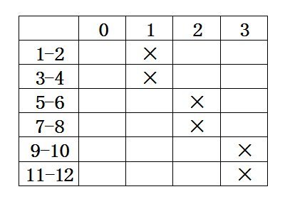
Figure 5: Wiring diagram for the Baomain Rotary Cam Switch. This diagram shows a table with rows representing terminal pairs (1-2, 3-4, etc.) and columns representing switch positions (0, 1, 2, 3). An 'X' indicates a closed contact at a given position.
Interpreting the Wiring Diagram (Figure 5):
- The rows represent pairs of terminals (e.g., 1-2, 3-4, 5-6, 7-8, 9-10, 11-12).
- The columns represent the switch positions (0, 1, 2, 3).
- An 'X' in a cell indicates that the corresponding terminal pair is connected (closed) at that switch position.
- Position 0: All contacts are open. This is the 'OFF' position.
- Position 1: Terminals 1-2 and 3-4 are connected.
- Position 2: Terminals 5-6 and 7-8 are connected.
- Position 3: Terminals 9-10 and 11-12 are connected.
Important Note on Common Connections: This switch design typically requires the user to provide external jumper wires to create common connections if multiple circuits need to share a common input or output. For example, if you need a common input for positions 1, 2, and 3, you would connect the input to one terminal (e.g., terminal 1), and then jumper terminal 1 to terminal 5 and terminal 9. The outputs would then be taken from terminals 2, 6, and 10 respectively, depending on the desired circuit configuration.
Always verify continuity with a multimeter after wiring and before applying power to ensure correct connections and prevent short circuits.
5. Operating Instructions
The Baomain Rotary Cam Switch operates by rotating the handle to select one of the four distinct positions (0, 1, 2, 3).
- Position 0 (OFF): In this position, all internal contacts are open, ensuring no current flow through any connected circuits. This is the default 'off' or 'neutral' state.
- Position 1: Rotating the handle to '1' closes the contacts for terminal pairs 1-2 and 3-4, activating the circuit(s) connected to these terminals.
- Position 2: Rotating the handle to '2' closes the contacts for terminal pairs 5-6 and 7-8, activating the circuit(s) connected to these terminals.
- Position 3: Rotating the handle to '3' closes the contacts for terminal pairs 9-10 and 11-12, activating the circuit(s) connected to these terminals.
The switch provides a solid 'clunk' feedback when transitioning between positions, indicating a positive engagement of the contacts.
6. Maintenance
The Baomain Rotary Cam Switch is designed for durability and requires minimal maintenance. However, regular checks can prolong its lifespan and ensure safe operation.
- Cleaning: Periodically clean the exterior of the switch with a dry, soft cloth. Do not use abrasive cleaners or solvents. Ensure power is off before cleaning.
- Inspection: Annually inspect the terminals for any signs of loose connections, corrosion, or overheating. Tighten any loose screws. Check the switch handle for smooth operation and ensure it clicks firmly into each position.
- Environmental Conditions: Ensure the switch is operating within its specified environmental conditions (temperature, humidity) to prevent premature wear.
7. Troubleshooting
If you encounter issues with your Baomain Rotary Cam Switch, consider the following common problems and solutions:
- Switch Not Functioning / No Output:
- Verify that the power supply to the switch is active.
- Check all wiring connections for tightness and correct placement according to the wiring diagram (Figure 5). Loose connections are a common cause of intermittent operation or failure.
- Ensure that any necessary external jumper wires for common connections are correctly installed (refer to Section 4.2).
- Use a multimeter to check for continuity across the appropriate terminal pairs at each switch position as per the diagram.
- Incorrect Operation / Unexpected Circuit Activation:
- Re-verify your wiring against the diagram (Figure 5). A common mistake is misinterpreting the terminal connections for each position.
- Confirm that the physical switch model number (SZW26-40/0-3.3) matches the one you intended to purchase and install. In rare cases, units may be mislabeled.
- Handle Stiff or Not Clicking Firmly:
- Ensure the switch is mounted correctly and not under undue stress from the panel.
- Inspect for any foreign objects obstructing the rotary mechanism.
- If the issue persists, the internal mechanism may be damaged, and the switch may need replacement.
If troubleshooting steps do not resolve the issue, contact Baomain customer support or a qualified electrician.
8. Warranty and Support
Specific warranty details for the Baomain SZW26-40/0-3.3 Rotary Cam Switch are not provided in the product information. For warranty claims, technical support, or further inquiries, please contact the seller or visit the official Baomain store: