1. Product Overview
The Throttle Position Sensor (TPS) and Accelerator Pedal Position Sensor (APPS) are critical components in your vehicle's engine management system. This sensor provides information to the Engine Control Module (ECM) regarding the accelerator pedal's position, which determines the driver's requested engine speed and power output. A properly functioning sensor ensures accurate fuel delivery and ignition timing, contributing to optimal engine performance and efficiency.

Image 1.1: Platinum Performance Parts TPS APPS Throttle Position Sensor.
1.1. Compatibility
This TPS APPS sensor is designed for direct replacement in specific Dodge Ram models equipped with the 5.9L Cummins diesel engine.
- 1998-2004 Dodge Ram 2500 with 5.9L Cummins Engine
- 1998-2004 Dodge Ram 3500 with 5.9L Cummins Engine

Image 1.2: Visual representation of compatible vehicles and the sensor.
2. Installation Instructions
Follow these steps carefully for proper installation of the APPS sensor. Refer to the diagrams for visual guidance.
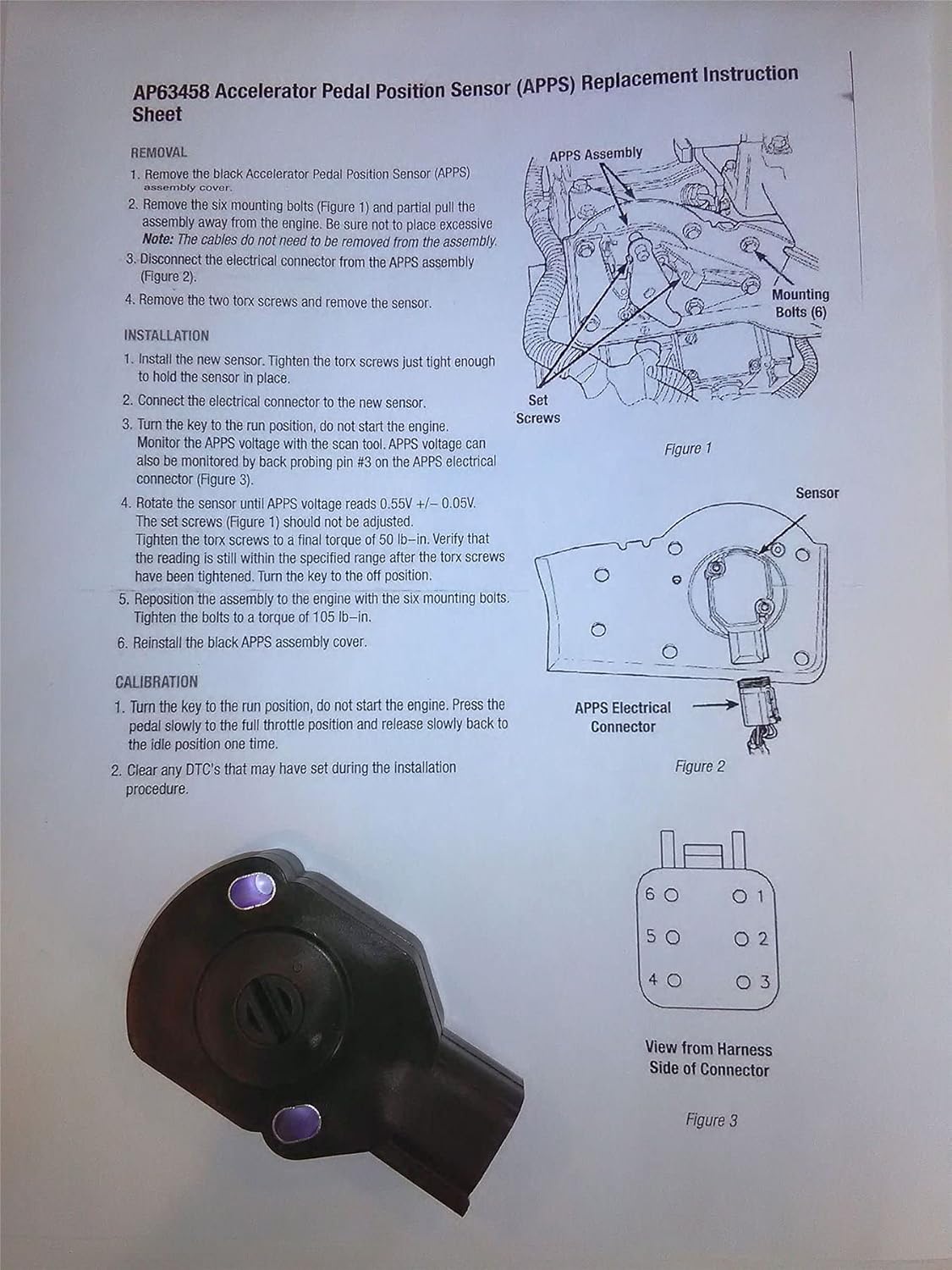
Image 2.1: Original APPS Replacement Instruction Sheet.
2.1. Tools Required (Recommended)
- Torx bit set
- Socket wrench set
- Multimeter or scan tool for voltage measurement
- Torque wrench
2.2. Removal Procedure
- Remove the black Accelerator Pedal Position Sensor (APPS) assembly cover.
- Remove the six mounting bolts (refer to Figure 1 in Image 2.1) and partially pull the assembly away from the engine. Avoid applying excessive force. The cables do not need to be removed from the assembly.
- Disconnect the electrical connector from the APPS assembly (refer to Figure 2 in Image 2.1).
- Remove the two Torx screws and then remove the old sensor.
2.3. Installation Procedure
- Install the new sensor. Tighten the Torx screws just enough to hold the sensor in place, allowing for slight rotation during calibration.
- Connect the electrical connector to the new sensor.
- Turn the ignition key to the RUN position, but do not start the engine.
- Measure the APPS voltage using a scan tool. Alternatively, the APPS voltage can be monitored by back-probing pin #3 on the APPS electrical connector (refer to Figure 3 in Image 2.1 for pinout).
- Carefully rotate the sensor until the APPS voltage reads 0.55V +/- 0.05V. The set screws (refer to Figure 1 in Image 2.1) should not be adjusted.
- Once the correct voltage is achieved, tighten the Torx screws to a final torque of 50 lb-in. Verify that the voltage reading remains within the specified range after tightening. Then, turn the ignition key to the OFF position.
- Reposition the APPS assembly to the engine using the six mounting bolts. Tighten these bolts to a torque of 105 lb-in.
- Reinstall the black APPS assembly cover.

Image 2.2: Diagram showing sensor mounting hole and connector location.

Image 2.3: Detailed view of the 6-pin connector from the harness side.
3. Calibration Procedure
After installation, perform the following calibration steps to ensure proper sensor operation.
- Turn the ignition key to the RUN position, but do not start the engine.
- Slowly press the accelerator pedal to the full throttle position, then slowly release it back to the idle position. Perform this action one time.
- Clear any Diagnostic Trouble Codes (DTCs) that may have been set during the installation procedure using a suitable scan tool.
4. Troubleshooting Common Issues
If you experience any of the following symptoms after installation, refer to these troubleshooting tips:
- Idling Problems: If the engine idles roughly or inconsistently, re-check the sensor's voltage calibration (0.55V +/- 0.05V) and ensure all connections are secure.
- Sudden Speed Drops or Loss of Power: This can indicate an incorrect sensor reading. Verify the calibration and inspect the wiring for any damage or loose connections.
- Check Engine Light (CEL) Illumination: If the CEL comes on, retrieve any stored DTCs using a scan tool. Common codes related to the APPS sensor include P2121, P0121, P0122, and P0123. Address the specific code by re-checking installation, calibration, and wiring integrity.
- Incorrect Voltage Reading: If the APPS voltage cannot be set to 0.55V +/- 0.05V, ensure the sensor is correctly seated and the Torx screws are only hand-tight before final adjustment. If the issue persists, the sensor itself may be faulty.
5. Product Specifications
| Specification | Value |
|---|---|
| Item Model Number | 5303157 |
| Brand | Platinum Performance Parts |
| Maximum Supply Voltage | 12 Volts (DC) |
| Mounting Type | Bolt-on |
| Output Type | Digital |
| Package Dimensions | 3 x 2.5 x 2.5 inches |
| Item Weight | 2.4 ounces |

Image 5.1: Physical dimensions of the sensor.
6. Warranty and Support
This product is manufactured by Platinum Performance Parts. For any questions regarding installation, troubleshooting, or product performance, please contact the manufacturer directly. Refer to your purchase documentation for specific warranty details and contact information.