MXBAOHENG SF-104
MXBAOHENG SF-104 Digital Temperature Controller
User Manual
1. Product Overview
The MXBAOHENG SF-104 is an integrated intelligent temperature control unit designed for refrigeration systems. It provides precise temperature regulation, defrost control, and evaporator fan management. This controller is suitable for direct control of compressors up to 1P (including 1P) and features a digital display for easy monitoring.
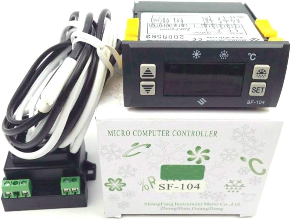
Figure 1.1: MXBAOHENG SF-104 Digital Temperature Controller and included components.
2. Key Features
- Integrated intelligent control for compressors (up to 1P), evaporator fans, and defrost heating wires.
- Digital temperature display with high accuracy.
- Manual and automatic defrost functions.
- Time and temperature-terminated defrost cycles.
- Parameter lock and self-diagnosis capabilities.
- External sealed 12V AC transformer for power supply.
- Two NTC temperature probes (storage temperature, defrost control) with 2m length.
3. Technical Specifications
| Parameter | Value |
|---|---|
| External Transformer Output | AC 12V |
| Temperature Probe Type | NTC (2 probes, 2m length) |
| Temperature Display Range | -45°C to 66°C (-45°F to 150°F) |
| Temperature Display Accuracy | ±1°C (±2°F) |
| Control Temperature Range | -45°C to 45°C (-45°F to 120°F) |
| Default Control Temperature | 0°C (32°F) |
| Dimensions (Controller) | 77 x 35 x 60mm (3.03"L x 1.38"W) |
| Hole Size (Installation) | 71 x 29mm |
| Operating Environment Temperature | -10°C to 60°C (14°F to 140°F) |
| Operating Environment Humidity | 20% ~ 90% (non-condensing) |
| Compressor Relay Contact Capacity | Normally Open 20A/250VAC |
| Defrost Heating Wire Relay Contact Capacity | Normally Open 10A/250VAC |
| Evaporator Fan Relay Contact Capacity | Normally Open 5A/250VAC |
| Material | Plastic |
| Item Weight | 1 Pound |
4. Setup and Installation
Proper installation is crucial for the safe and effective operation of the SF-104 controller. Refer to the wiring diagram on the unit and the precautions below.
4.1 Components Overview

Figure 4.1: Main components of the SF-104 package.
4.2 Wiring Instructions
The SF-104 controller requires connection to a 12V AC power source via the provided external transformer, as well as connections for the compressor, defrost heating wire, and evaporator fan. Two NTC temperature probes must also be connected.

Figure 4.2: Top view of the SF-104 controller showing the wiring diagram.

Figure 4.3: Angled view of the SF-104 controller displaying the terminal block for connections.
4.3 Power Transformer Connection
The external sealed transformer converts the main AC voltage to 12V AC for the controller. Ensure correct input and output connections.

Figure 4.4: External power transformer for the SF-104 controller.

Figure 4.5: Terminals on the external power transformer.
4.4 Installation Precautions
- To prevent high-frequency interference, route the probe cable in conjunction with power lines or control lines separately. 12V low-voltage lines should not run parallel with high-voltage wiring.
- The probe should be installed head-on. The defrost probe should be placed in a metal film evaporator where ice is thickest and not close to the heating wire.
- If the installation requires, extend the probe line up to 100m without re-examination.
- The thermostat cannot install a drip place.

Figure 4.6: Excerpt from the manual detailing function description and installation precautions.
5. Operating Instructions
5.1 Temperature Control
The controller manages the compressor based on the set temperature and hysteresis. The compressor starts after a delay if the storage temperature exceeds (control temperature + hysteresis) and stops when the storage temperature is less than the control temperature. To protect the compressor, it will not restart until a minimum delay time (X4 parameter) has passed.
5.2 Electric Defrost Function
The defrost heating wire activates only if the defrost termination probe temperature is below the set temperature (F3 parameter). The controller can initiate manual or automatic defrost cycles. During defrost, the defrost indicator light illuminates, and the compressor and evaporator fan stop. If the defrost termination probe temperature is higher than the defrost termination temperature, or if the defrost time limit is reached, the heating wire stops working. The compressor starts two minutes after dripping into normal temperature patterns, and the evaporator fan starts one minute after the compressor starts.
If the defrost interval is set to "00", the automatic defrost function is canceled.
5.3 Defrost Locked Storage Temperature Display
When setting parameter F4 = 1, the display locks the temperature inside the defrost probe, showing the defrost start temperature. After defrosting, the storage temperature display is delayed by 20 minutes (or until the control temperature is reached) before returning to normal display. During this delay, the defrost lights will flash.
5.4 Non-Normal Operating Mode
If the thermostat probe experiences a short circuit or high temperature (greater than 66°C / 150°F), the display will show "HH". If the storage temperature probe is open or low (less than -45°C / -45°F), the display will show "LL". In these cases, the compressor will run for 30 minutes and then stop for 15 minutes.
If the defrost probe experiences a short circuit, open circuit, or overload, the defrost function will terminate, limited only by the defrost time control.
6. Maintenance
To ensure the longevity and optimal performance of your SF-104 controller, regular maintenance is recommended:
- Cleaning: Periodically wipe the controller's exterior with a soft, dry cloth. Avoid using abrasive cleaners or solvents.
- Connection Checks: Annually inspect all wiring connections to ensure they are secure and free from corrosion. Loose connections can lead to erratic behavior or component damage.
- Probe Inspection: Check the temperature probes for any physical damage or signs of wear. Ensure they are properly positioned and clean for accurate readings.
- Environmental Conditions: Ensure the operating environment remains within the specified temperature and humidity ranges to prevent damage to internal components.
7. Troubleshooting
This section addresses common issues you might encounter with the SF-104 controller.
7.1 Display Errors
- "HH" Display: Indicates a thermostat probe short circuit or high temperature (above 66°C / 150°F). Check the probe and its wiring.
- "LL" Display: Indicates an open circuit or low temperature (below -45°C / -45°F) for the storage temperature probe. Verify probe connection and integrity.
7.2 Temperature Reading Inaccuracies
- Ensure the temperature probes are correctly installed and positioned according to Section 4.4.
- Verify that the probe cables are not running parallel to high-voltage lines, which can cause interference.
- The SF-104 supports both Celsius and Fahrenheit display. Refer to the programming instructions (typically involving the SET button) to switch between units if needed.
7.3 Defrost Malfunctions
- If defrost is not initiating, check the F3 parameter (defrost termination temperature) and ensure the defrost probe is functioning correctly.
- If the defrost interval parameter is set to "00", automatic defrost is disabled. Adjust this parameter if automatic defrost is desired.
- For defrost probe short circuit, open circuit, or overload, the defrost function will terminate. Inspect the defrost probe and its connections.
8. Warranty and Support
For detailed warranty information, please refer to the documentation provided with your purchase or contact MXBAOHENG customer support.
Additional support resources:
- User Manual (PDF): Download PDF Manual
- MXBAOHENG Store: Visit MXBAOHENG Official Store
For technical assistance or service inquiries, please contact MXBAOHENG customer service directly.
Ask a question about this manual
Ask about setup, troubleshooting, compatibility, parts, safety, or missing instructions. Manuals+ will review the question and use this page’s manual context to help answer it.