
1. Introduction
The HiLetgo SIM800L GPRS GSM Breakout Module is a compact and low-power solution for integrating quad-band GSM/GPRS network capabilities into your projects. This module enables remote data transmission via GPRS and SMS messages, and supports voice calls. Designed for ease of use, it communicates with microcontrollers through a UART port and responds to standard AT commands.
2. Key Features
- Quad-Band Support: Operates on 850/900/1800/1900MHz frequencies, ensuring global GSM network compatibility.
- Low Power Consumption: Features power-saving techniques, achieving as low as 1mA in sleep mode.
- UART Communication: Easily interfaces with microcontrollers via a serial UART port.
- AT Command Interface: Supports 3GPP TS 27.007, 27.005, and SIMCOM enhanced AT Commands with auto baud detection.
- Voice & SMS: Capable of making and receiving voice calls (with external speaker/microphone) and sending/receiving SMS messages.
- GPRS Data: Supports GPRS data transmission (TCP/IP, HTTP).
- Additional Features: Includes FM radio broadcast scanning and control ports for buzzer and vibrational motor.
3. Package Contents
Upon opening your HiLetgo SIM800L module package, you should find the following items:
- 1x SIM800L GPRS GSM Breakout Module
- 1x External Antenna
- Pin Headers (typically 90-degree or straight, for connection)
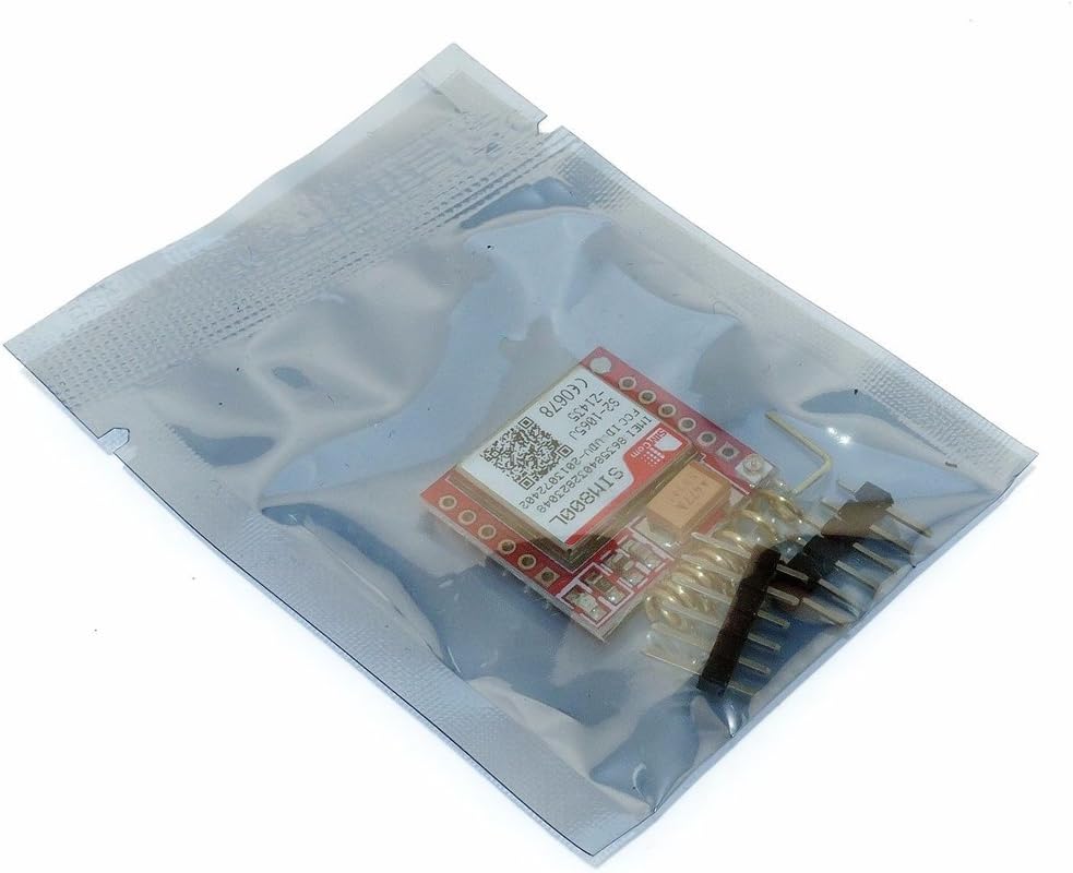
Figure 3.1: HiLetgo SIM800L GPRS GSM Breakout Module and antenna inside anti-static packaging.
4. Component Overview
Familiarize yourself with the main components and connection points of the SIM800L module.

Figure 4.1: Top view of the SIM800L module. This image displays the top side of the SIM800L module, highlighting the SIMCOM SIM800L chip, various components, and the pin headers for connections. Key identifiers like IMEI (863584032823048) and FCC ID (UDV-2013072402) are visible on the chip.
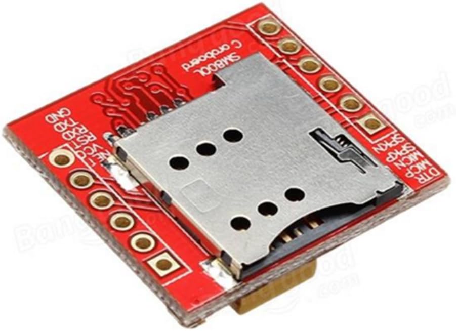
Figure 4.2: Bottom view of the SIM800L module with SIM card slot. This image shows the underside of the SIM800L module, featuring the mini SIM card slot. The pin labels for power (VCC, GND), UART communication (RXD, TXD), and other functions are clearly visible on the board.

Figure 4.3: External antenna. This image illustrates the external antenna provided with the module. It consists of a flexible PCB antenna element and a coaxial cable with an IPEX/U.FL connector for attachment to the module.
5. Specifications
| Feature | Description |
|---|---|
| Brand | HiLetgo |
| Model Name | 3-01-1090-A |
| Connectivity Technology | GSM, GPRS |
| Wireless Communication Standard | 900 MHz Radio Frequency (Quad-Band 850/900/1800/1900MHz) |
| Compatible Devices | 8051, AVR, ARM, PIC, Arduino, Raspberry Pi |
| Working Voltage | 3.5V ~ 4.2V |
| Processor Count | 1 |
6. Setup Guide
6.1 Power Supply
The SIM800L module requires a stable power supply within the range of 3.5V to 4.2V. It is crucial to provide sufficient current, especially during network registration and data transmission, as current draw can spike. A dedicated power supply or a buck converter capable of delivering at least 2A is recommended.
6.2 SIM Card Insertion
The module uses a Mini SIM card. Carefully insert the SIM card into the slot on the underside of the module. Ensure the card is oriented correctly as indicated by the diagram on the board or the SIM slot itself. Incorrect insertion can prevent the module from recognizing the SIM card.
6.3 Antenna Connection
Connect the provided external antenna to the IPEX/U.FL connector on the module. Ensure a secure connection for optimal signal reception and transmission.
6.4 UART Connection to Microcontroller
Connect the module to your microcontroller (e.g., Arduino, Raspberry Pi) using the UART pins:
- VCC: Connect to your microcontroller's 3.5V-4.2V power supply.
- GND: Connect to the common ground of your system.
- RXD: Connect to your microcontroller's TX pin.
- TXD: Connect to your microcontroller's RX pin.
- RST: (Optional) Connect to a digital pin on your microcontroller for software reset.
Ensure that the logic levels of your microcontroller are compatible with the SIM800L module (typically 3.3V logic). If your microcontroller uses 5V logic, a logic level shifter may be required for the RXD/TXD lines to prevent damage.
7. Operating Instructions
The SIM800L module is controlled using AT commands sent via the UART interface. The module supports auto baud rate detection, simplifying initial setup.
7.1 Basic Communication (AT Commands)
To begin, establish a serial connection with the module from your microcontroller or a serial terminal. Send the command AT and the module should respond with OK. This confirms basic communication.
7.2 Network Registration
After powering on, the module will attempt to register with a GSM network. The Net Light (usually a red LED) will flash at different rates:
- Slow flash (e.g., 1 flash every 3 seconds): Module is registered to the network.
- Fast flash (e.g., 1 flash per second): Module is searching for a network or not registered.
You can check network registration status using AT commands like AT+CREG?.
7.3 Sending SMS Messages
To send an SMS, use the following sequence of AT commands:
AT+CMGF=1(Set SMS to text mode)AT+CMGS="<phone_number>"(Replace <phone_number> with recipient's number)- Type your message.
- Send
Ctrl+Z(ASCII 26) to terminate and send the message.
7.4 GPRS Data Transmission
For GPRS data, you will need to configure the Access Point Name (APN) for your SIM card's network provider and then establish a GPRS connection. This typically involves commands like AT+CSTT, AT+CIICR, and AT+CIFSR, followed by TCP/IP commands (e.g., AT+CIPSTART, AT+CIPSEND).
7.5 Voice Calls
To make a voice call, connect an external 8Ω speaker and an electret microphone to the appropriate pins (SPKP, SPKN, MICP, MICN). Use the command ATD<phone_number>; to dial a number.
8. Maintenance
- Handle with Care: The module contains sensitive electronic components. Avoid dropping or subjecting it to excessive force.
- Keep Dry: Protect the module from moisture and liquids, which can cause short circuits and damage.
- Cleanliness: Keep the module free from dust and debris. Use a soft, dry brush or compressed air for cleaning if necessary.
- Proper Power: Always ensure the power supply is within the specified voltage range (3.5V-4.2V) and can provide sufficient current. Over-voltage or under-current can lead to unstable operation or damage.
- Antenna Connection: Ensure the antenna is always connected when the module is powered on and attempting to communicate, as operating without an antenna can potentially damage the RF section.
9. Troubleshooting
- Module Not Responding to AT Commands:
- Check UART connections (TX to RX, RX to TX).
- Verify baud rate settings. The module supports auto baud, but ensure your terminal/microcontroller is sending data at a common rate (e.g., 9600, 115200).
- Confirm power supply is stable and within 3.5V-4.2V.
- SIM Card Not Detected:
- Ensure the SIM card is inserted correctly and fully seated in the slot.
- Verify the SIM card is active and not locked (e.g., requires a PIN).
- Confirm the SIM card is a Mini SIM.
- Cannot Register to Network (Net Light Flashing Fast):
- Check antenna connection.
- Ensure your location has 2G GSM network coverage. In some regions (e.g., USA), 2G networks are being phased out or are no longer supported by certain carriers.
- Verify SIM card is active and has service.
- Ensure adequate power supply; network registration can draw significant current.
- Module Gets Very Hot:
- This can indicate excessive current draw or a faulty module. Check your power supply voltage and current capabilities.
- Ensure there are no short circuits on the board.
10. Warranty and Support
HiLetgo products are designed for reliability and performance. For technical support, troubleshooting assistance, or any issues you encounter with your product, please contact us directly.
Email: support@hiletgo.com
Please include your product model number (SIM800L, 3-01-1090-A) and a detailed description of the issue when contacting support to help us assist you more efficiently.