HiLetgo 4350281287
HiLetgo NE555 DC 12V Delay Timer Switch Adjustable Module User Manual
Model: 4350281287
1. Product Overview
The HiLetgo NE555 DC 12V Delay Timer Switch Adjustable Module is designed to provide a timed delay for various electrical applications. This module utilizes the NE555 timer IC to offer an adjustable delay period from 0 to 10 seconds. It is suitable for controlling both DC and AC loads, making it versatile for automotive, industrial, and home automation projects.
Key Features:
- Main Chip: NE555 timer IC.
- Operating Voltage: 12V DC.
- Adjustable Delay Time: 0 to 10 seconds, controlled by a potentiometer.
- Relay Output: Capable of controlling AC 250V/10A or DC 0-30V/10A equipment (maximum 2000W).
- Indicators: Includes an input power indicator and a relay activation indicator.
- Protection: Features relay freewheeling protection.
2. Specifications
| Specification | Value |
|---|---|
| Main Chip | NE555 |
| Working Voltage | 12V DC |
| Delay Time Range | 0 to 10 seconds (adjustable) |
| Maximum Control Load (AC) | 250V / 10A |
| Maximum Control Load (DC) | 0-30V / 10A |
| Maximum Control Power | 2000W |
| Connector Type | Screw Terminals |
| Contact Type | Normally Closed (NC), Normally Open (NO) |
| Mounting Type | Surface Mount |
| Dimensions | 6.8 CM x 2.1 CM (approx. 2.68 x 0.83 inches) |
| Item Weight | 0.352 ounces |
3. Module Components and Connections
Familiarize yourself with the various components and connection points on the delay timer module.

Figure 3.1: Labeled components of the HiLetgo NE555 Delay Timer Module. This image shows the power input terminals (+ and -), the potentiometer for delay adjustment, the NE555 chip, the relay, and the relay output terminals (COM, CK, CB).
- Power Supply Terminals: Connect 12V DC power to the '+' and '-' terminals.
- Potentiometer (W104): Used to adjust the delay time. Turning clockwise increases the delay.
- Relay Output Terminals:
- COM (Common): The common terminal for the relay switch.
- CK (Normally Open - NO): Connected to COM when the relay is activated (sucked).
- CB (Normally Closed - NC): Connected to COM when the relay is inactive (released).
- Power Light: Indicates when the module is receiving power.
- Relay Suction Indicator Light: Illuminates when the relay is activated.

Figure 3.2: Top view of the HiLetgo NE555 Delay Timer Module, showing the relay, potentiometer, and screw terminals.

Figure 3.3: Bottom view of the HiLetgo NE555 Delay Timer Module, showing the solder points and general PCB layout.
4. Setup and Wiring
Proper wiring is crucial for the safe and correct operation of the module. Ensure all power is disconnected before making any connections.
4.1 Power Supply Connection
Connect a 12V DC power source to the module's power input terminals. The '+' terminal is for positive, and the '-' terminal is for negative (ground).
4.2 Load Wiring for DC Appliances
This configuration is suitable for controlling DC-powered devices, such as in automotive applications to delay the power supply to prevent current surges during ignition.

Figure 4.1: Wiring diagram for controlling DC power supply appliances. The delay module is connected between the ignition switch/car battery and the DC electric load (e.g., car DVD, navigator). The module delays power to the appliance after the car starts.
- Connect the 12V DC power source (e.g., car battery or ignition switch output) to the module's '+' and '-' terminals.
- Connect the positive terminal of your DC appliance to one of the relay's output terminals (either CK for Normally Open or CB for Normally Closed, depending on desired behavior).
- Connect the negative terminal of your DC appliance to the negative terminal of your power source.
- Connect the relay's COM terminal to the positive output of the module's power source.
Note: For a delay-on function (appliance turns on after delay), connect the appliance to the CK (Normally Open) terminal. For a delay-off function (appliance turns off after delay), connect to the CB (Normally Closed) terminal.
4.3 Load Wiring for AC 220V Household Appliances
This configuration allows the module to control AC household appliances up to 2000W.

Figure 4.2: Wiring diagram for controlling AC 220V household appliances. The module's 12V DC power supply is separate from the 220V AC load. The AC load is switched via the relay contacts.
- Connect a separate 12V DC power source to the module's '+' and '-' terminals. This power source is for the module itself, not the AC load.
- For the AC load, connect one wire from the 220V AC power supply to the relay's COM terminal.
- Connect the other wire from the 220V AC power supply to one terminal of your AC appliance.
- Connect the remaining terminal of your AC appliance to either the CK (Normally Open) or CB (Normally Closed) terminal of the relay, depending on your desired delay behavior.
Caution: Working with AC 220V can be dangerous. Ensure all connections are secure and insulated. If you are unsure, consult a qualified electrician.
5. Operating Instructions
The module operates by providing a fixed cycle delay for the relay. When power is applied, the relay will immediately activate (suck) for a set duration, then release for the same duration, repeating this cycle as long as power is supplied.
5.1 Adjusting Delay Time
The delay time (T) is adjustable from 0 to 10 seconds using the onboard potentiometer (W104).
Figure 5.1: The potentiometer (blue component labeled W104) is used to adjust the delay time. Turning it clockwise increases the delay.
- Locate the blue potentiometer on the module.
- Use a small screwdriver to turn the potentiometer.
- Turning the potentiometer clockwise will increase the delay time.
- Turning the potentiometer counter-clockwise will decrease the delay time.
Note: The potentiometer may require multiple full turns to cover the entire 0-10 second range. Adjust incrementally and test the delay until the desired timing is achieved.
5.2 Delay Time Formula
The delay time (T) is determined by the formula: T = 1.1 * R * C, where R is the resistance of the potentiometer and C is the capacitance of C1 (100uF). For example, with C1 = 100uF and R = 100KΩ, T = 1.1 * 100,000 * 0.0001 = 11 seconds.
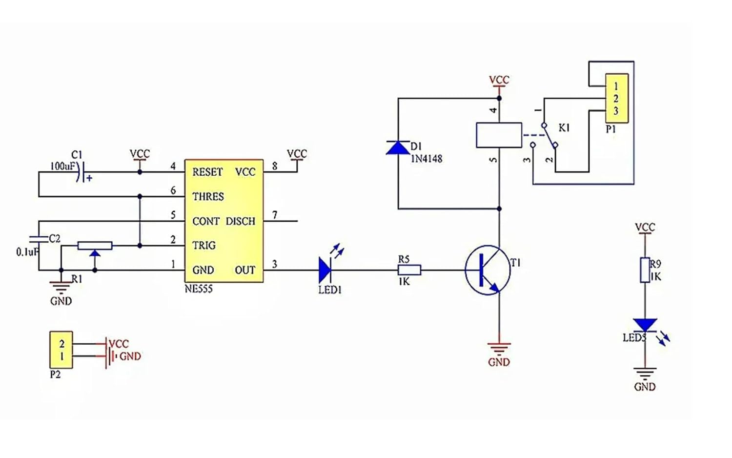
Figure 5.2: Circuit diagram of the NE555 Delay Timer Module, showing the NE555 IC, capacitor C1, and resistor R1 (part of the timing circuit).
Increasing the value of the potentiometer or the capacitor C1 can extend the maximum delay time beyond 10 seconds if modifications are made.
6. Maintenance
The HiLetgo NE555 Delay Timer Module is a low-maintenance device. Follow these general guidelines to ensure its longevity:
- Keep Dry: Avoid exposing the module to moisture or liquids, which can cause short circuits and damage.
- Cleanliness: Keep the module free from dust and debris. Use a soft, dry brush or compressed air for cleaning if necessary.
- Temperature: Operate the module within its specified temperature range. Avoid extreme heat or cold.
- Secure Connections: Periodically check all screw terminal connections to ensure they are tight and secure, especially in environments with vibration.
- Power Supply: Ensure the input power supply is stable and within the 12V DC specification. Voltage fluctuations can affect performance and lifespan.
7. Troubleshooting
If you encounter issues with your NE555 Delay Timer Module, refer to the following troubleshooting steps:
- Module Not Powering On (No Power Light):
- Verify that the 12V DC power supply is connected correctly to the '+' and '-' terminals.
- Check the power supply itself to ensure it is providing 12V DC.
- Inspect wiring for any loose connections or breaks.
- Relay Not Activating/Deactivating (No Relay Indicator Light):
- Ensure the module is powered on (power light is illuminated).
- Check the potentiometer setting. If set to minimum, the delay might be too short to observe.
- Verify the load connected to the relay is within the specified voltage and current limits (10A, 2000W max). Overloading can damage the relay.
- Inspect the relay for any visible damage.
- Incorrect Delay Time or No Adjustment:
- Turn the potentiometer multiple full rotations to ensure you are covering its full range. Some potentiometers require many turns.
- Ensure the potentiometer is not damaged or loose.
- Verify that the capacitor C1 is correctly installed and not damaged.
- Relay Chattering or Unstable Operation:
- This can indicate an unstable power supply. Ensure your 12V DC source is clean and stable.
- Check for electromagnetic interference (EMI) if operating near high-power devices.
- Ensure connections to the relay are secure and not intermittent.
- Load Not Switching:
- Confirm the load is correctly wired to the COM and either CK (NO) or CB (NC) terminals.
- Test the load independently to ensure it is functional.
- Check for continuity across the relay contacts when activated/deactivated (with power off for safety).
8. Warranty and Support
Specific warranty information for the HiLetgo NE555 DC 12V Delay Timer Switch Adjustable Module is not provided in the product details. For any issues or support inquiries, please contact the seller or manufacturer directly through the platform where the product was purchased.
When contacting support, please provide the following information:
- Product Model Number: 4350281287
- ASIN: B01DK8NJNI
- Description of the issue.
- Steps taken to troubleshoot.
Related Documents - 4350281287
 |
NE555 Delay Relay Module User Guide & Specifications Comprehensive guide for the NE555-based delay relay module. Covers specifications, applications, and technical characteristics for 5V and 12V models, including the QF-RD02 and YL-21 variants. |
 |
JK11 Cycle Dual Adjustable Multi-function Relay Module: User Guide and Specifications Explore the JK11 Cycle Dual Adjustable Multi-function Relay Module. This guide details its features, single and cycle operating modes, time range settings (0-24 hours), voltage options (5V, 12V, 24V), and application examples. Learn about jumper configurations, potentiometer adjustments, and important electrical safety notes for this industrial-grade timer relay. |
 |
Gaqqee AC 220V Timer Relay Delay Switch Module Technical specifications and features for the Gaqqee AC 220V Timer Relay Delay Switch Module, an adjustable timing board for household and industrial applications. |
 |
Aideepen JK11 Cycle Timer Delay Relay Module User Manual Comprehensive user manual for the Aideepen JK11 adjustable cycle timer delay relay module. Learn about features, operating modes, wiring, and configuration. |
 |
T3231 Digital Time Delay Relay: Specifications, Instructions, and Operation Comprehensive guide to the T3231 Digital Time Delay Relay, featuring adjustable timing ranges, dual LED displays, and various operational modes. Includes detailed specifications, setup instructions, parameter configurations, and connection diagrams for AC and DC power supplies. |
 |
T3230 Digital Time Delay Relay Module - User Manual & Specifications Detailed information on the T3230 digital time delay relay module, including specifications, operating instructions, and visual descriptions. Features adjustable timing ranges and dual LED display for precise control. |
Ask a question about this manual
Ask about setup, troubleshooting, compatibility, parts, safety, or missing instructions. Manuals+ will review the question and use this page’s manual context to help answer it.