1. Product Overview
The HiLetgo MAX7219 8-Digital Segment LED Display Module is an integrated serial input/output common-cathode display driver designed to interface microprocessors with 8-digit 7-segment digital LED displays. It can also be used with bar graph displays or 64 individual LEDs.
Key features include an on-chip BCD encoder, multi-channel scanning loop, segment word driver, and an 8x8 static RAM for data storage. A single external resistor sets the current for each LED segment. The module supports flicker-free displays and cascading multiple units.
This module is compatible with 5V and 3.3V microcontrollers, including popular platforms like Arduino, 51, AVR, and STM32.

Figure 1: Two HiLetgo MAX7219 8-Digital Segment LED Display Modules, showing the front view of the LED segments and included pin headers.
2. Setup and Wiring
The MAX7219 module utilizes a convenient four-wire serial interface for connection to microprocessors. Only three I/O ports are required to drive an eight-digit display.
2.1 Pin Connections
The module typically includes pin headers for easy connection. Ensure correct polarity when connecting power.
- VCC: Power supply (5V or 3.3V, compatible with your microcontroller).
- GND: Ground connection.
- DIN (Data In): Serial data input.
- CS (Chip Select/LOAD): Load data into the MAX7219.
- CLK (Clock): Serial clock input.
Important Safety Note: Connecting VCC and GND in reverse polarity will damage the chip. Always double-check your wiring before applying power.
2.2 Example Wiring (Conceptual)
For a 51 series microcontroller, if the P0 port is used for data lines, it may require an external pull-up resistor. If your device lacks an internal pull-up resistor on P0, consider using other available I/O ports for data lines.
A typical connection might look like this (specific I/O pins can be defined in your program):
- VCC: Connect to 5V (or 3.3V)
- GND: Connect to GND
- DIN: Connect to Microcontroller I/O Pin (e.g., P0.0)
- CS: Connect to Microcontroller I/O Pin (e.g., P0.1)
- CLK: Connect to Microcontroller I/O Pin (e.g., P0.2)

Figure 2: Front view of the MAX7219 module, highlighting the LED segments and the connection points for pin headers.

Figure 3: Back view of the MAX7219 module, illustrating the MAX7219 integrated circuit and the labeled connection pins (VCC, GND, DIN, CS, CLK).

Figure 4: Close-up view of the male pin headers supplied with the module, used for making electrical connections.
3. Operating Instructions
The MAX7219 driver allows for individual addressing of each digit, meaning data can be updated without rewriting the entire display. It also offers options for data encoding or no encoding, depending on your application requirements.
3.1 Serial Communication
Communication with the MAX7219 is achieved via a serial interface. Data is sent bit by bit using the DIN, CLK, and CS pins. Refer to the MAX7219 datasheet for detailed serial communication protocols and command sets.
3.2 Brightness Control
The device includes analog and digital brightness control features. This allows users to adjust the intensity of the LED segments to suit various lighting conditions or power consumption requirements.
3.3 Scan-Limit Register
A scan-limit register enables the user to display 1 to 8 bits of data, providing flexibility for applications that do not require all eight digits to be active simultaneously.
3.4 Low-Power Shutdown Mode
The entire device incorporates a 150µA low-power shutdown mode, which can be utilized to conserve energy when the display is not actively in use.
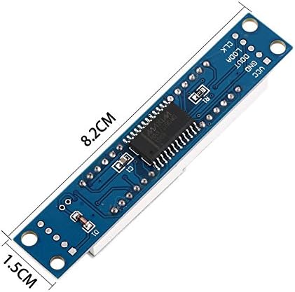
Figure 5: An angled view of the MAX7219 module, demonstrating the clarity of the 8-digital segment display when active.
4. Maintenance
The HiLetgo MAX7219 module is designed for durability. To ensure its longevity and proper function, handle the module with care, avoiding excessive force or bending. Keep the module clean and free from dust and moisture. No specific routine maintenance is required for this component.
5. Troubleshooting
- Display Not Lighting Up or Malfunctioning:
- Power Connection: Verify that VCC and GND are connected correctly and not reversed. Incorrect polarity will damage the chip.
- P0 Port Pull-up Resistor: If using a 51 series MCU and the P0 port, ensure a pull-up resistor is present. If not, consider using other I/O ports for data lines.
- Wiring Integrity: Check all four serial interface connections (VCC, GND, DIN, CS, CLK) for loose connections or incorrect pin assignments.
- Code Logic: Review your microcontroller code for correct initialization, data transmission, and command sequences for the MAX7219.
- Individual Segments or Digits Not Working:
- Solder Joints: Inspect solder joints on the module, especially around the MAX7219 chip and the LED segments. In rare cases, a cold solder joint might prevent a segment from lighting. This typically requires advanced soldering skills to correct.
- Data Corruption: Ensure your data transmission is clean and free from noise.
- Display Appears Crooked or Misaligned:
- This can sometimes occur due to manufacturing variances. While it does not affect functionality, it may impact aesthetic integration into an enclosure.
6. Specifications
| Feature | Detail |
|---|---|
| Model Number | 3-01-1067 |
| Display Type | 8-Digital 7-Segment LED (Common Cathode) |
| Driver IC | MAX7219 |
| Operating Voltage | 3.3V - 5V |
| Interface | 4-wire Serial (SPI compatible) |
| LED Color | Red (as per typical product images) |
| Digit Size | 0.36 inches |
| Module Dimensions | Approximately 8.2 cm x 1.5 cm (3.23 x 0.59 inches) |
| Weight | Approximately 0.915 ounces (26 grams) |
| Compatibility | Arduino, 51, AVR, STM32 microcontrollers |

Figure 6: Dimensions of the MAX7219 module, showing approximate length and width measurements.
7. Warranty and Support
For specific warranty information regarding your HiLetgo MAX7219 8-Digital Segment LED Display Module, please refer to the purchase documentation or contact the seller directly. Support for this product is typically provided by the vendor from whom it was purchased.
You may also visit the HiLetgo Store on Amazon for additional product information or to contact their support channels.