
1. Introduction
This manual provides essential information for the safe operation, setup, maintenance, and troubleshooting of your Precision Matthews PM-25MV Milling Machine with an installed 3-Axis Digital Readout (DRO). Please read this manual thoroughly before operating the machine to ensure proper usage and to prevent injury or damage.
2. Safety Instructions
Operating machinery can be hazardous. Adhere to all safety precautions to minimize risks.
- Read the Entire Manual: Understand all instructions and warnings before operating.
- Wear Personal Protective Equipment (PPE): Always wear safety glasses, hearing protection, and appropriate clothing. Avoid loose clothing, jewelry, and long hair that can get caught in moving parts.
- Ensure a Safe Work Environment: Keep the work area clean, well-lit, and free of clutter. Do not operate in damp or wet conditions.
- Electrical Safety: Ensure the machine is properly grounded. Do not operate with damaged cords or plugs. Disconnect power before performing maintenance or adjustments.
- Secure Workpiece: Always securely clamp the workpiece to the table before beginning any operation.
- Use Correct Tools: Use only sharp, correctly sized cutting tools for the material being machined.
- Never Leave Machine Unattended: Turn off the machine and ensure all moving parts have stopped before leaving the work area.
- Machine Stability: Ensure the machine is securely mounted to its stand and the stand is stable on a level surface.
3. Components Overview
The PM-25MV Milling Machine is a robust tool designed for precision machining. Below is an overview of its main components.
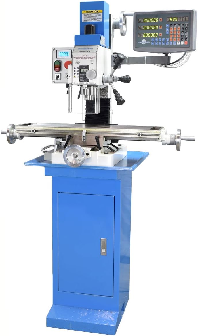
Figure 3.1: Overall view of the Precision Matthews PM-25MV Milling Machine with its stand and integrated 3-Axis Digital Readout system. This image displays the main body, spindle head, work table, control panel, and the DRO display unit.
- Spindle Head: Houses the motor, spindle, and speed control mechanisms.
- Work Table: The surface where workpieces are clamped for machining. It moves along the X and Y axes.
- Column: Supports the spindle head and allows for Z-axis movement.
- Base & Stand: Provides stability for the entire machine. The stand includes storage.
- Control Panel: Contains power switches, speed controls, and emergency stop button.
- 3-Axis Digital Readout (DRO): Provides precise digital display of X, Y, and Z axis positions.
- Handwheels: Used for manual movement of the X, Y, and Z axes.
4. Setup
4.1 Unpacking and Inspection
- Carefully remove the machine and all components from the packaging.
- Inspect for any shipping damage. Report any damage immediately to the carrier and supplier.
- Verify all components listed in the packing list are present.
4.2 Assembly and Mounting
The PM-25MV comes with a dedicated stand. Proper mounting is crucial for stability and safe operation.
- Position the stand on a level, sturdy surface capable of supporting the machine's weight.
- Carefully lift the milling machine body and align its base with the mounting holes on the stand. It is recommended to use appropriate lifting equipment and assistance due to the machine's weight.
- Secure the machine to the stand using the provided bolts, washers, and nuts. Ensure all fasteners are tightened securely.

Figure 4.1: Close-up view of the machine's base, showing the mounting points and the routing of the DRO sensor cables. This illustrates how the machine is secured to its stand.

Figure 4.2: Detailed view of the bolts and nuts used to secure the milling machine to its stand. Proper tightening of these fasteners is essential for machine stability.
4.3 Electrical Connection
- Ensure the machine's power switch is in the 'OFF' position.
- Connect the power cord to a suitable grounded electrical outlet. Refer to the machine's specifications for voltage and amperage requirements.
4.4 DRO System Setup
The 3-Axis DRO system is pre-installed. Verify all sensor cables are securely connected to the DRO display unit. Consult the separate DRO manual for detailed calibration and operation instructions.
5. Operating Instructions
5.1 Power On/Off
- To power on, press the green 'ON' button on the control panel.
- To power off, press the red 'OFF' button or the emergency stop button.
5.2 Spindle Speed Control
The PM-25MV features a brushless DC motor with belt drive, allowing for variable speed control.
- Adjust the spindle speed using the speed control knob on the control panel.
- Refer to machining charts for appropriate speeds based on material and cutter diameter.
5.3 Table Movement (X, Y, Z Axes)
The work table can be moved manually using the handwheels for precise positioning.
- X-Axis: Moves the table left and right.
- Y-Axis: Moves the table forward and backward.
- Z-Axis: Moves the spindle head up and down.
5.4 Digital Readout (DRO) Operation
The 3-Axis DRO provides real-time position feedback for all three axes. Consult the DRO manual for specific functions such as zeroing, absolute/incremental modes, and bolt hole patterns.
5.5 Basic Milling Operations
Before starting any milling operation, ensure the workpiece is securely clamped, the correct cutting tool is installed, and the spindle speed is set appropriately. Always make light cuts initially and gradually increase depth as needed.
6. Maintenance
Regular maintenance ensures the longevity and accuracy of your milling machine.
6.1 Cleaning
- After each use, clean chips and debris from the table, ways, and spindle area using a brush or shop vacuum.
- Wipe down all exposed metal surfaces with a clean cloth to prevent rust.
6.2 Lubrication
- Regularly lubricate the lead screws, gibs, and other moving parts with appropriate machine oil.
- Refer to the lubrication points indicated in the machine diagram (if available) or consult the manufacturer's recommendations.
6.3 Adjustments
- Periodically check and adjust the gibs for proper tension to eliminate play in the table and head movements.
- Inspect belts for wear and tension. Replace or adjust as necessary.
7. Troubleshooting
This section addresses common issues you might encounter with your PM-25MV Milling Machine.
| Problem | Possible Cause | Solution |
|---|---|---|
| Machine does not power on | No power to outlet; Emergency Stop engaged; Power switch faulty | Check power supply; Disengage E-stop; Contact support |
| Excessive vibration or noise | Loose mounting bolts; Unbalanced workpiece; Dull cutting tool; Worn bearings | Tighten bolts; Balance workpiece; Replace tool; Contact support |
| Inaccurate DRO readings | Loose sensor cables; Dirty scales; DRO unit malfunction | Check connections; Clean scales; Consult DRO manual or support |
| Table movement is stiff or jerky | Lack of lubrication; Gibs too tight; Debris in ways | Lubricate ways and lead screws; Adjust gibs; Clean ways |
8. Specifications
- Model: PM-25MV
- Table Size: 7-1/8" x 27-1/2"
- Motor Type: Brushless DC Motor
- Drive System: Belt Drive Head
- Digital Readout: 3-Axis DRO Installed
- Material: Metal construction
- Manufacturer: Precision Matthews
9. Warranty and Support
Precision Matthews products are designed for durability and performance. For warranty information, technical support, or service inquiries, please refer to the warranty card included with your purchase or visit the official Precision Matthews website. When contacting support, please have your machine model (PM-25MV) and serial number available.