1. Product Overview
The SEAFLO 12V 5.5 GPM 60 PSI Water Diaphragm Pressure Pump (Model SFDP1-055-060-51) is a self-priming, positive displacement diaphragm pump designed for various liquid transfer applications. It features a 5-chamber design, a smart pressure switch for automatic operation, and an internal bypass for reduced cycling. This pump is capable of running dry without damage.

Image 1.1: The SEAFLO 12V 5.5 GPM 60 PSI Water Diaphragm Pressure Pump.
Key Features:
- Flow Rate: 5.5 Gallons Per Minute (20.0 LPM)
- Pressure: 60 PSI
- Priming Capabilities: 6 feet (1.8 m) suction lift
- Inlet/Outlet Ports: 1/2″-14 MNPT
- Electrical: 12V DC, 16 AWG leads with 2-Pin connector
- Diaphragm: 5-chamber positive displacement design
- Protection: Capable of being run dry, built-in thermal protection
- Noise Reduction: Rubber base for anti-vibration and low noise operation
2. Safety Information
Read all instructions carefully before installation and operation. Failure to follow these instructions may result in product damage, personal injury, or property damage.
- Always disconnect power before servicing the pump.
- Ensure proper voltage (12V DC) is supplied to the pump. Incorrect voltage can cause damage.
- Do not pump flammable liquids. This pump is designed for water and non-flammable liquids only.
- Protect the pump from freezing temperatures.
- Ensure all plumbing connections are secure to prevent leaks.
- Install a fuse or circuit breaker in the positive (+) lead as close to the power source as possible. Refer to specifications for appropriate amperage.
3. Package Contents
Verify that all items are present in the package:
- 1x SEAFLO 12V 5.5 GPM 60 PSI Water Diaphragm Pressure Pump
- 2x 1/2" Barbed Hose Adaptors
- 1x 50 Mesh Inlet Strainer
- 1x Set of Instructions (this manual)
4. Setup and Installation
4.1 Mounting
Mount the pump in a dry, well-ventilated area. The pump can be mounted horizontally or vertically. Use the integrated rubber feet to minimize vibration and noise. Ensure there is sufficient space around the pump for ventilation and access for maintenance.

Image 4.1: Rubber base for anti-vibration and standard mounting bracket dimensions.
4.2 Plumbing Connections
The pump has 1/2"-14 MNPT inlet and outlet ports. Use the provided 1/2" barbed hose adaptors for hose connections. Ensure all connections are tight and leak-free. It is recommended to install the 50 mesh inlet strainer on the inlet side to prevent debris from entering the pump.
- Inlet: Connect the water supply to the inlet port. The pump is self-priming up to 6 feet (1.8 m).
- Outlet: Connect the outlet port to your water system.
- Avoid kinks or sharp bends in hoses that could restrict flow.

Image 4.2: Top view of the pump, indicating inlet and outlet connections.
4.3 Electrical Connections
Connect the pump to a 12V DC power source. The pump comes with 16 AWG leads and a 2-pin connector.
- Connect the red wire to the positive (+) terminal of the 12V DC power source.
- Connect the black wire to the negative (-) terminal of the 12V DC power source.
- Install an appropriately sized fuse or circuit breaker (refer to specifications for max current draw) in the positive (+) lead, as close to the battery as possible.
5. Operating Instructions
Once properly installed and connected, the pump operates automatically via its integrated smart pressure switch.
5.1 Initial Start-up and Priming
- Ensure all plumbing connections are secure and the inlet strainer is clean.
- Open a faucet or outlet in your water system.
- Apply 12V DC power to the pump. The pump will begin to run, drawing water and pushing air out of the system.
- Allow the pump to run until a steady, air-free flow of water is achieved from the open faucet.
- Close the faucet. The pump's pressure switch will detect the pressure buildup and automatically shut off.
5.2 Automatic Operation
The smart pressure switch provides automatic start and stop functionality. When a faucet is opened, the system pressure drops, and the pump automatically turns on. When the faucet is closed, the pressure rises, and the pump automatically turns off. This mimics the experience of home water usage.

Image 5.1: Smart Pressure Switch operation.
5.3 Internal Bypass Technology
The pump incorporates internal bypass technology to regulate pressure and reduce frequent on/off cycling. This helps maintain a steady water flow and extends the pump's lifespan by reducing stress on components.

Image 5.2: Internal Bypass for reduced cycling and smooth operation.
6. Maintenance
Regular maintenance ensures optimal performance and longevity of your pump.
6.1 Inlet Strainer Cleaning
Periodically inspect and clean the 50 mesh inlet strainer to prevent debris from entering the pump and restricting flow. A clogged strainer can lead to reduced performance or pump damage.
- Disconnect power to the pump.
- Remove the strainer housing.
- Rinse the mesh screen under clean water to remove any accumulated debris.
- Reassemble the strainer, ensuring a tight seal.
6.2 General Inspection
- Check all plumbing connections for leaks. Tighten as necessary.
- Inspect electrical wiring for any signs of wear or damage.
- Ensure the pump is securely mounted and the rubber feet are intact.
6.3 Winterization
If the pump will be exposed to freezing temperatures, it must be winterized to prevent damage.
- Drain all water from the pump and plumbing system.
- Alternatively, flush the system with non-toxic RV antifreeze.
7. Troubleshooting
This section provides solutions to common issues you might encounter.
| Problem | Possible Cause | Solution |
|---|---|---|
| Pump does not turn on | No power; Blown fuse/tripped breaker; Loose wiring; Faulty pressure switch | Check power supply; Replace fuse/reset breaker; Secure all electrical connections; Contact support if switch is faulty. |
| Low flow or no water output | Clogged inlet strainer; Air leak in suction line; Restricted inlet/outlet; Low voltage; Pump not primed | Clean inlet strainer; Check all suction line connections; Clear any obstructions; Verify 12V DC supply; Re-prime the pump. |
| Pump runs continuously or cycles rapidly | Water leak in system; Open faucet; Faulty pressure switch; Air in system | Check for leaks in plumbing; Ensure all faucets are closed; Contact support if switch is faulty; Bleed air from system by opening a faucet. |
| Excessive noise/vibration | Loose mounting; Debris in pump head; Air in system | Secure pump mounting; Disconnect power and inspect pump head (if comfortable); Bleed air from system. |
8. Specifications
Technical specifications for the SEAFLO 12V 5.5 GPM 60 PSI Water Diaphragm Pressure Pump (Model SFDP1-055-060-51).

Image 8.1: Detailed specifications for SEAFLO 55-Series pumps.
| Specification | Value |
|---|---|
| Model Number | SFDP1-055-060-51 |
| Voltage | 12 Volts DC |
| Maximum Flow Rate | 5.5 Gallons Per Minute (20.8 LPM) |
| Shut-Off Pressure | 60 PSI (4.2 BAR) |
| Maximum Current Draw | 17A |
| Priming Capabilities | 6 feet (1.8 m) suction lift |
| Inlet/Outlet Ports | 1/2″-14 MNPT |
| Maximum Liquid Temperature | 140°F (60°C) |
| Material (Diaphragm) | Santoprene |
| Material (Valves) | EPDM |
| Housing Material | Nylon / Polypropylene |
| Dimensions (Approx.) | 8.5" L x 5.75" W x 5.16" H (216mm x 146mm x 131mm) |
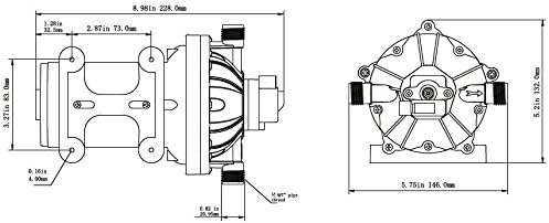
Image 8.2: Pump dimensions diagram.
9. Warranty and Support
SEAFLO products are designed for reliability and durability. This product comes with a 4-year warranty, ensuring peace of mind regarding its quality and performance.
9.1 Warranty Information
The 4-year warranty covers defects in materials and workmanship under normal use and service. Please retain your proof of purchase for warranty claims. The warranty does not cover damage caused by improper installation, misuse, neglect, freezing, or unauthorized modifications.
9.2 Customer Support
For technical assistance, warranty claims, or any questions regarding your SEAFLO pump, please contact SEAFLO customer support. Refer to the official SEAFLO website or your purchase documentation for contact details.


