Datakom D-500
Datakom D-500 Automatic Generator Control Panel User Manual
Model: D-500 (ASIN: B018HBP18Y)
1. Introduction
The Datakom D-500 is an advanced Automatic Mains Failure (AMF) generator control panel designed for comprehensive generator management. It features a user-friendly web interface and an integrated GSM modem, enabling remote monitoring, control, and communication. This manual provides essential information for the proper installation, operation, and maintenance of your D-500 unit.
2. Key Features and Communication
The D-500 offers a wide range of features for efficient generator control and communication:
- Automatic Mains Failure (AMF) operation
- Integrated Web Server for remote access and control
- GSM modem for SMS and remote communication
- SNMP communication for network integration
- Multiple communication interfaces: Ethernet, USB, RS-232, GSM
- Data logging and event history
- Remote display panel support
- Micro SD and USB Flash memory support

Figure 2.1: Overview of D-500 communication capabilities, including E-mail, GSM-SMS, SNMP, Embedded Web Server, PC, HMI Display, PLC, and Remote Display Panel connections.
The D-500 also supports advanced software programs for monitoring and programming:
- Web Server: Provides digital monitoring, event log display, and web programming capabilities.
- Rainbow Plus Program: Offers SCADA functionality, waveform display, harmonic analysis, and programming.
- Rainbow SCADA Program: Enables complete fleet display on a map and comprehensive monitoring & control screens.
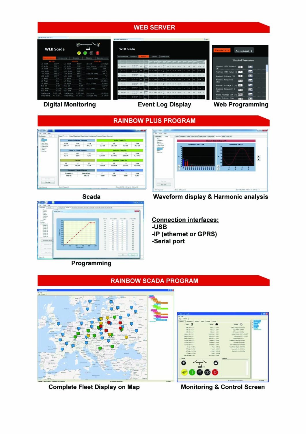
Figure 2.2: Screenshots illustrating the Web Server interface, Rainbow Plus Program for SCADA and analysis, and Rainbow SCADA Program for fleet management.
3. Installation and Connections
Proper installation and wiring are crucial for the safe and reliable operation of the D-500. Refer to the wiring diagram below for typical connections.

Figure 3.1: Detailed wiring diagram showing connections for Alternator, Mains, Load, RS-232, USB, Ethernet, SIM card, GSM Antenna, and various inputs/outputs. Note: Battery Negative must be grounded.
3.1. Power Connections
- Connect the main power supply to the designated terminals.
- Ensure the battery negative is properly grounded to prevent electrical issues.
3.2. Generator and Mains Connections
- Connect the alternator output (L1, L2, L3, N) to the corresponding terminals.
- Connect the mains supply (L1, L2, L3, N) to the designated mains input terminals.
- Connect the load to the appropriate output terminals.
3.3. Communication Connections
- Ethernet: Connect an Ethernet cable for network communication and web interface access.
- USB: Use the USB host or device ports for programming and data transfer.
- RS-232: Connect serial devices for communication.
- GSM: Insert a SIM card and connect the GSM antenna for remote SMS and data communication.
3.4. Sensor and Input Connections
- Connect engine sensors (e.g., oil pressure, water temperature) to the designated analog and digital input terminals.
- Ensure all connections are secure and correctly polarized.
4. Operation
The D-500 control panel provides intuitive controls and a clear display for monitoring and operating your generator.
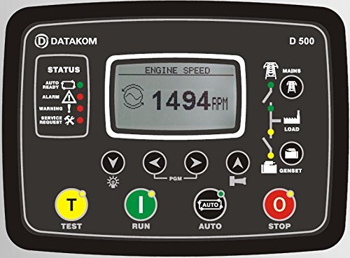
Figure 4.1: Front view of the D-500 control panel, showing the display, status indicators, and control buttons.
4.1. Control Panel Overview
- Display: Shows real-time information such as engine speed, voltage, frequency, and operational status.
- Status Indicators: LEDs indicate the current state of the system (e.g., Auto Ready, Alarm, Warning, Service Request).
- Navigation Buttons: Used to scroll through menus and adjust settings.
4.2. Basic Operations
- TEST Button (T): Initiates a generator test run.
- RUN Button (I): Starts the generator manually.
- AUTO Button: Activates Automatic Mains Failure (AMF) mode, allowing the generator to start and stop automatically based on mains power availability.
- STOP Button (O): Stops the generator manually.
4.3. Web Interface Operation
Access the D-500's web interface by connecting it to a network and entering its IP address into a web browser. The web interface allows for:
- Real-time monitoring of all generator parameters.
- Viewing event logs and alarms.
- Remote starting and stopping of the generator.
- Configuration of system settings and parameters.
5. Maintenance
Regular maintenance ensures the longevity and optimal performance of your D-500 control panel.
- Cleaning: Keep the control panel clean and free from dust and moisture. Use a soft, dry cloth for cleaning. Do not use abrasive cleaners or solvents.
- Connections: Periodically check all wiring connections for tightness and signs of corrosion. Loose connections can lead to intermittent operation or damage.
- Firmware Updates: Check the Datakom website for available firmware updates to ensure your unit has the latest features and bug fixes.
- Environmental Conditions: Ensure the operating environment adheres to the specified temperature and humidity ranges to prevent damage.
6. Troubleshooting
This section provides basic troubleshooting steps for common issues. For more complex problems, contact Datakom technical support.
- No Power to Panel:
- Check battery connections and voltage.
- Verify power supply fuses.
- Generator Fails to Start:
- Ensure the unit is in AUTO or RUN mode.
- Check fuel level and engine oil.
- Verify all safety shutdowns (e.g., low oil pressure, high temperature).
- No Remote Communication (Web/GSM):
- Check Ethernet cable connection and network settings.
- Verify SIM card installation and GSM signal strength.
- Ensure correct IP address and port settings for web access.
- Error Messages on Display:
- Refer to the D-500's detailed alarm list in the full technical manual for specific error codes and their remedies.
7. Technical Specifications
Below are the key technical specifications for the Datakom D-500 control panel:
| Parameter | Value |
|---|---|
| Alternator voltage | 0 to 300 V-AC (Ph-N) |
| Alternator frequency | 0-600 Hz |
| Mains voltage | 0 to 300 V-AC (Ph-N) |
| Mains frequency | 0-600 Hz |
| Topology | 1-2-3 Phase with or without neutral |
| DC Supply Range | 8.0 to 36.0 V-DC |
| V-A-Hz Accuracy | 0.5% + 1 digit |
| kW-kVA-kVAr Accuracy | 1.0% + 1 digit |
| Current consumption | 500 mA-DC max. |
| Current inputs | from current transformers, ../5A. |
| Digital inputs | input voltage 0 to 36 V-DC. |
| Analog input range | 0-5000 mVs. |
| Main relay and configurable outputs | 16Amps@250V DC output: Protected MOSFET semiconductor outputs, rated 1A@60VDC. |
| Cranking dropouts | survives 0V for 100ms. |
| Magnetic pickup voltage | 0.5 to 30 V-AC. |
| Magnetic pickup frequency | 0 to 20000 Hz. |
| Charge Alternator Excitation | 2W. |
| Ethernet Port | 10/100 Mbits. |
| USB Device | USB 2.0 Full speed. |
| USB Host | USB 2.0 Full speed. |
| RS-485 Port | selectable baud rate. |
| RS-232 Port | selectable baud rate. |
| Operating temperature | -20°C to 70°C (-4 to +158°F). |
| Storage temperature | -30°C to 80°C (-40 to +176°F). |
| Maximum humidity | 95% non-condensing. |
| IP Protection | IP54 from front panel, IP30 from the rear. |
| Dimensions | 200 x 148 x 46mm (WxHxD). |
| Panel Cut-out Dimensions | 176 x 121 mm minimum. |
| Weight | 450 g (approx.). |
| Case Material | High temperature, non-flammable ABS/PC. |
| Mounting | Front panel mounted with rear retaining plastic brackets. |
| EU Directives Conformity | - 2006/95/EC (low voltage) - 2004/108/EC (electro-magnetic compatibility) |
| Norms of reference | EN 61010 (safety requirements) EN 61326 (EMC requirements) |
| UL Compatibility | UL 508 - Industrial Control Equipment |
| CSA Compatibility | CAN/CSA C22.2 No. 14-2005 - Industrial Control Equipment |
8. Warranty and Support
Datakom products are designed for reliability and performance. For specific warranty terms and conditions, please refer to the documentation provided with your purchase or visit the official Datakom website.
For technical assistance, troubleshooting beyond this manual, or spare parts inquiries, please contact Datakom customer support or your authorized dealer. Provide your product model (D-500) and ASIN (B018HBP18Y) when seeking support.
Manufacturer: Datakom