
Hobby King DST-1200
Turnigy Aerodrive DST-1200 Brushless Outrunner Motor User Manual
Model: DST-1200
1. Introduction
Thank you for choosing the Turnigy Aerodrive DST-1200 Brushless Outrunner Motor. This motor is designed for remote-controlled aircraft, specifically park flyers and multi-rotor applications, offering a powerful yet lightweight solution. This manual provides essential information for the safe and efficient operation, setup, and maintenance of your motor. Please read this manual thoroughly before installation and use.
2. Safety Information
WARNING: Failure to follow these safety instructions may result in injury or damage to the product or property.
- Always disconnect the battery from the motor and Electronic Speed Controller (ESC) when not in use or during maintenance.
- Ensure all wiring connections are secure and properly insulated to prevent short circuits.
- Keep hands, loose clothing, and other objects clear of the rotating propeller and motor during operation. The propeller can cause severe injury.
- Operate the motor in a well-ventilated area.
- Do not exceed the recommended voltage and current ratings specified for this motor.
- Regularly inspect the motor for any signs of damage, loose connections, or wear.
- Keep out of reach of children.
- Use only compatible propellers and mounting hardware.
3. Package Contents
Verify that all items are present in your package:
- 1x Turnigy Aerodrive DST-1200 Brushless Outrunner Motor
- 1x Propeller Adapter
- Mounting Screws (various sizes)
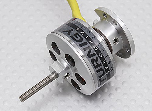
Figure 1: Turnigy Aerodrive DST-1200 Brushless Outrunner Motor and included accessories. The image shows the compact motor with its bell housing, a separate propeller adapter, and a small bag of mounting screws.
4. Setup and Installation
4.1 Motor Mounting
The DST-1200 motor can be mounted using the included screws. Ensure the motor is securely fastened to your aircraft's motor mount. Use thread-locking compound on screws if necessary to prevent loosening due to vibration.
- Identify the mounting holes on your aircraft's motor mount.
- Align the motor with the mounting holes.
- Secure the motor using the appropriate mounting screws. Do not overtighten.
4.2 ESC Connection
Connect the three motor wires to your Electronic Speed Controller (ESC). The order of connection may affect the motor's rotation direction. If the motor spins in the wrong direction, swap any two of the three motor wires.
- Connect the three motor wires to the corresponding output wires of your ESC.
- Ensure connections are firm and insulated (e.g., with heat shrink tubing).
4.3 Propeller Installation
Install the propeller using the provided propeller adapter. Ensure the propeller is balanced and securely attached to prevent vibration and potential failure.
- Slide the propeller adapter onto the motor shaft.
- Place the propeller onto the adapter, ensuring it is oriented correctly for thrust.
- Secure the propeller with the retaining nut or collet, tightening firmly but without excessive force.
4.4 Battery Connection
Connect your flight battery to the ESC. Ensure the battery voltage matches the recommended range for the motor and ESC (2-3 Cell LiPo, 7.4-11.1V).
- Connect the battery's positive (+) terminal to the ESC's positive (+) input.
- Connect the battery's negative (-) terminal to the ESC's negative (-) input.
- Double-check polarity before connecting to avoid damage.
5. Operating Instructions
5.1 Pre-Flight Checks
Before operating the motor, perform the following checks:
- Ensure all connections are secure.
- Verify the propeller is securely attached and balanced.
- Check for any obstructions around the propeller.
- Confirm battery is fully charged and correctly connected.
- Ensure your radio transmitter and receiver are properly bound and functioning.
5.2 Initial Run
When first operating the motor, apply throttle slowly and observe its behavior. The motor should spin smoothly without excessive noise or vibration.
- With the aircraft secured, slowly advance the throttle.
- Observe the motor's rotation direction. If incorrect, refer to Section 4.2.
- Listen for unusual noises and check for excessive heat after a short run.
5.3 Performance Monitoring
During operation, monitor the motor's temperature. Excessive heat can indicate an overloaded motor, an undersized propeller, or an issue with the ESC. Adjust propeller size or flight duration as needed to keep the motor within safe operating temperatures.
6. Maintenance
Regular maintenance ensures the longevity and optimal performance of your motor.
- Cleaning: Keep the motor free from dirt, dust, and debris. Use compressed air or a soft brush to clean the motor's exterior and cooling fins.
- Bearing Inspection: Periodically check the motor bearings for smooth operation. If you notice any grinding or excessive play, the bearings may need replacement.
- Wiring and Connectors: Inspect all wires and connectors for signs of wear, fraying, or corrosion. Replace damaged components immediately.
- Storage: Store the motor in a clean, dry environment away from extreme temperatures and direct sunlight.
7. Troubleshooting
| Problem | Possible Cause | Solution |
|---|---|---|
| Motor does not spin. |
|
|
| Motor spins in wrong direction. |
|
|
| Motor overheats. |
|
|
| Excessive vibration. |
|
|
8. Specifications
Key technical specifications for the Turnigy Aerodrive DST-1200 Brushless Outrunner Motor:
| Feature | Detail |
|---|---|
| Model | DST-1200 |
| Brand | Hobby King |
| Kv (RPM/V) | 1200kv |
| Recommended Battery | 2~3 Cell LiPo (7.4~11.1V) |
| Max Current | 16A |
| No Load Current (11.1V) | 0.8A |
| Weight | 57g |
| Shaft Diameter | 3mm |
| Dimensions | 30mm x 50.7mm |
| Material | Plastic (housing, though motor core is metal) |
| Product Dimensions (packaging) | 2.6 x 1.6 x 1.5 inches |
| Item Weight (packaging) | 2 Pounds |
9. Warranty and Support
This Turnigy Aerodrive DST-1200 Brushless Outrunner Motor is covered by a manufacturer's warranty against defects in materials and workmanship. The specific terms and duration of the warranty may vary by region and retailer. Please retain your proof of purchase for warranty claims.
For technical support, warranty inquiries, or spare parts, please contact your retailer or the manufacturer, Hobby King, directly. Refer to their official website for the most up-to-date contact information and support resources.
Hobby King Official Website: https://hobbyking.com/
Ask a question about this manual
Ask about setup, troubleshooting, compatibility, parts, safety, or missing instructions. Manuals+ will review the question and use this page’s manual context to help answer it.