
ESUPPORT CXCP200
ESUPPORT 12V Car Auto Red LED Light Momentary Speaker Horn Push Button Metal Toggle Switch
User Instruction Manual
1. Introduction
The ESUPPORT 12V Car Auto Red LED Light Momentary Speaker Horn Push Button Metal Toggle Switch is a versatile component designed for various automotive applications. It can be used as a switch for additional equipment both inside and outside your vehicle. This manual provides detailed guidance for its proper installation and use.
2. Safety Information
- Always disconnect the vehicle's battery before performing any electrical work to prevent short circuits and electrical shock.
- Ensure all wiring connections are secure and properly insulated to prevent accidental contact.
- Do not exceed the specified voltage (12V) or current rating (5A) for the switch. Overloading can damage the switch and connected components.
- For loads exceeding 5 Amps, an automotive relay (sold separately) is required to protect the switch and ensure safe operation.
- If you are unsure about any installation steps, consult a qualified automotive electrician.
3. Product Features
- Momentary Type: The switch returns to its original position when the button is released.
- LED Illumination: Features a red LED light for visibility and aesthetic appeal.
- Durable Construction: Made from metal for enhanced durability.
- Standard Size: Requires a 19mm mounting hole for easy installation.
- Contact Configuration: 1 Normally Open (NO) and 1 Normally Closed (NC) contact.
- High Rating: Rated for 5A/250VAC, suitable for 12V DC automotive applications.
4. Package Contents
- 1 x ESUPPORT 12V LED Lighted Push Button Switch (Red Light)
5. Setup and Installation
Proper installation is crucial for the functionality and safety of your switch. Follow these steps carefully:
5.1 Mounting the Switch
- Choose a suitable location for the switch on your vehicle's dashboard or panel.
- Drill a 19mm (0.75 inch) diameter hole at the chosen location. Ensure the hole is clean and free of burrs.
- Insert the switch into the drilled hole. The switch is designed to sit snugly.
- Secure the switch using the provided nut on the back side of the panel. Tighten firmly but do not overtighten.
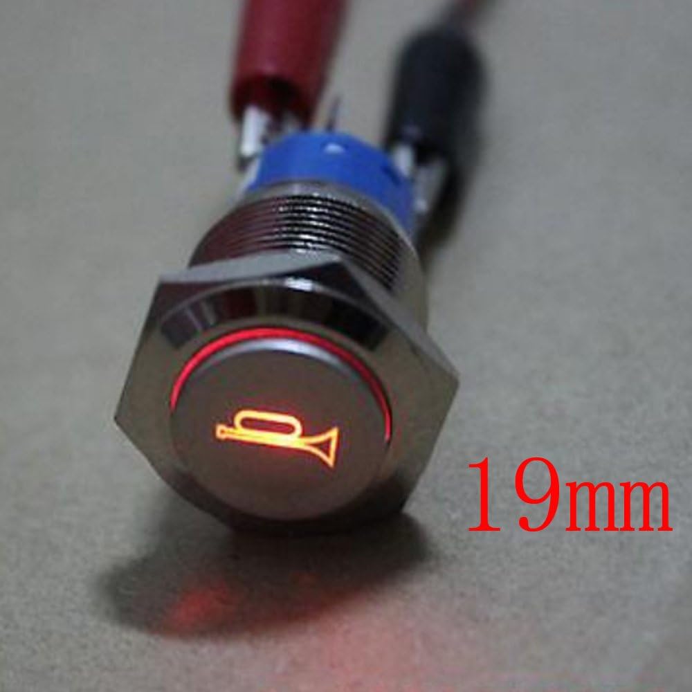
Image: The ESUPPORT push button switch, highlighting its 19mm diameter for mounting.
5.2 Wiring the Switch
The switch has five terminals: three for the switch contacts (COM, NO, NC) and two for the LED light (LED+, LED-). Understanding these connections is key.

Image: The ESUPPORT push button switch showing the rear terminals for wiring connections.
- COM (Common): This is the power input terminal for the switch function. Connect your positive power source to this terminal.
- NO (Normally Open): When the button is at rest (not pressed), there is no connection between COM and NO. When the button is pressed, the circuit between COM and NO is closed, allowing current to flow. Use this for functions that activate when the button is pressed (e.g., horn).
- NC (Normally Closed): When the button is at rest (not pressed), there is a connection between COM and NC. When the button is pressed, the circuit between COM and NC is opened, interrupting current flow. Use this for functions that are normally on and turn off when the button is pressed.
- LED+ (LED Positive): Connect the positive wire for the LED illumination to this terminal.
- LED- (LED Negative): Connect the negative (ground) wire for the LED illumination to this terminal.
Important Note on LED Wiring: To ensure the LED light is visible and functional, it is recommended to wire the LED independently from the switch's main function. For example, connect the LED positive to a circuit that is active when your vehicle's headlights or courtesy lights are on. This allows the LED to illuminate with your dash lights, making the switch visible without needing to press it. Connecting the LED directly to the switch's NO or NC terminals might only illuminate the LED when the button is pressed, which can be less practical.
Relay Requirement: For any electrical load exceeding 5 Amps, it is mandatory to use an automotive relay. The switch will then activate the relay, and the relay will handle the higher current load, protecting the switch from damage.

Image: A close-up view of the ESUPPORT push button switch with its red LED illumination active, showing the horn symbol.
6. Operating Instructions
Once properly installed and wired, operating the ESUPPORT momentary switch is straightforward:
- To Activate: Press the button firmly. The switch will engage the connected circuit (e.g., sound the horn) as long as the button is held down.
- To Deactivate: Release the button. The switch will return to its original state, disengaging the circuit.

Image: A hand pressing the ESUPPORT push button switch, demonstrating its momentary action.
7. Maintenance
The ESUPPORT push button switch is designed for durability and requires minimal maintenance.
- Cleaning: Periodically wipe the visible surface of the switch with a soft, damp cloth to remove dust and grime. Avoid using abrasive cleaners or solvents.
- Connection Check: Occasionally inspect the wiring connections at the back of the switch to ensure they remain secure and free from corrosion.
8. Troubleshooting
If you encounter issues with your ESUPPORT switch, consider the following common problems and solutions:
- Switch Not Activating Connected Device:
- Check all wiring connections for looseness or incorrect polarity.
- Verify that the COM terminal is receiving power.
- Ensure the correct output terminal (NO or NC) is used for your desired function.
- Confirm that the connected device is functioning correctly and not drawing excessive current (requiring a relay).
- LED Light Not Illuminating:
- Check the connections to the LED+ and LED- terminals. Ensure correct polarity (LED+ to positive, LED- to ground).
- Verify that the LED circuit is receiving 12V power.
- Ensure the LED is not damaged.
- Switch Feels Loose After Installation:
- Tighten the mounting nut on the back of the switch.
- Ensure the mounting hole is precisely 19mm; an oversized hole can cause looseness.
9. Specifications
| Specification | Value |
|---|---|
| Operation Mode | Push Button, Momentary |
| Current Rating | 5 Amps |
| Operating Voltage | 12 Volts (for LED and typical automotive use) |
| Contact Type | 1 Normally Open (NO), 1 Normally Closed (NC) |
| Connector Type | Plug In |
| Brand | ESUPPORT |
| Terminal | Button |
| Actuator Type | Push Button |
| Contact Material | Metal |
| International Protection Rating | IP54 |
| Number of Positions | 2 |
| Controller Type | Push Button |
| Control Method | Touch |
| Color | Red Light |
| Wattage | 1.25E+3 (1250W, likely for 250VAC rating) |
| Unit Count | 1 Count |
| Item Weight | 0.01 ounces |
| Package Dimensions | 4.41 x 3.46 x 0.71 inches |
| Item Model Number | CXCP200 |
| Manufacturer Part Number | CXCP200 |
| Bulb Type | LED |
| Date First Available | August 19, 2015 |
10. Warranty and Support
Specific warranty information for this product is not provided in the available data. For any warranty claims, technical support, or product inquiries, please contact the manufacturer, ESUPPORT, directly through their official channels or the retailer from whom the product was purchased.
Ask a question about this manual
Ask about setup, troubleshooting, compatibility, parts, safety, or missing instructions. Manuals+ will review the question and use this page’s manual context to help answer it.